Eureka AIR delivers breakthrough ideas for toughest innovation challenges, trusted by R&D personnel around the world.

Main tapping channel of blast furnace

A tapping channel and blast furnace technology, applied to blast furnaces, blast furnace details, blast furnace parts, etc., can solve problems such as unusable tapholes, unavailable maintenance, and unsatisfactory maintenance results, so as to reduce the probability of cracking and facilitate Removal and installation, the effect of accelerating damage

Inactive Publication Date: 2018-04-27
XINCHANG SHENGXIA MACHINERY PLANT
View PDF0 Cites 1 Cited by
  • Summary
  • Abstract
  • Description
  • Claims
  • Application Information

AI Technical Summary

Problems solved by technology

[0003] In the prior art, since the maintenance work must be carried out in front of the furnace, the corresponding tap hole cannot be used during the maintenance process of the tap trough, especially for small and medium-sized blast furnaces with a single tap hole. The ironmaking blast furnace must be shut down during the process, and currently the fastest maintenance operation for the tapping trough takes nearly 12 hours, and the work efficiency needs to be improved urgently
[0004] Due to the impact of maintenance duration on the normal operation of ironmaking blast furnaces, it is often impossible to achieve fine-level maintenance during maintenance. In order to ensure work efficiency, the time for maintenance operations is relatively tight, and in addition to the harsh environment accompanying the maintenance operations, workers often Unable to concentrate and meticulous work may lead to unsatisfactory repair results

Method used


Image

  • Main tapping channel of blast furnace
  • Main tapping channel of blast furnace
  • Main tapping channel of blast furnace

Examples


Embodiment Construction

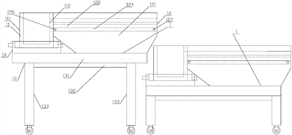
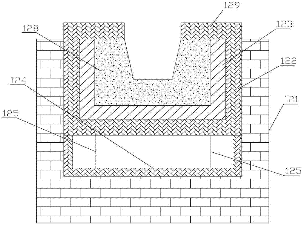
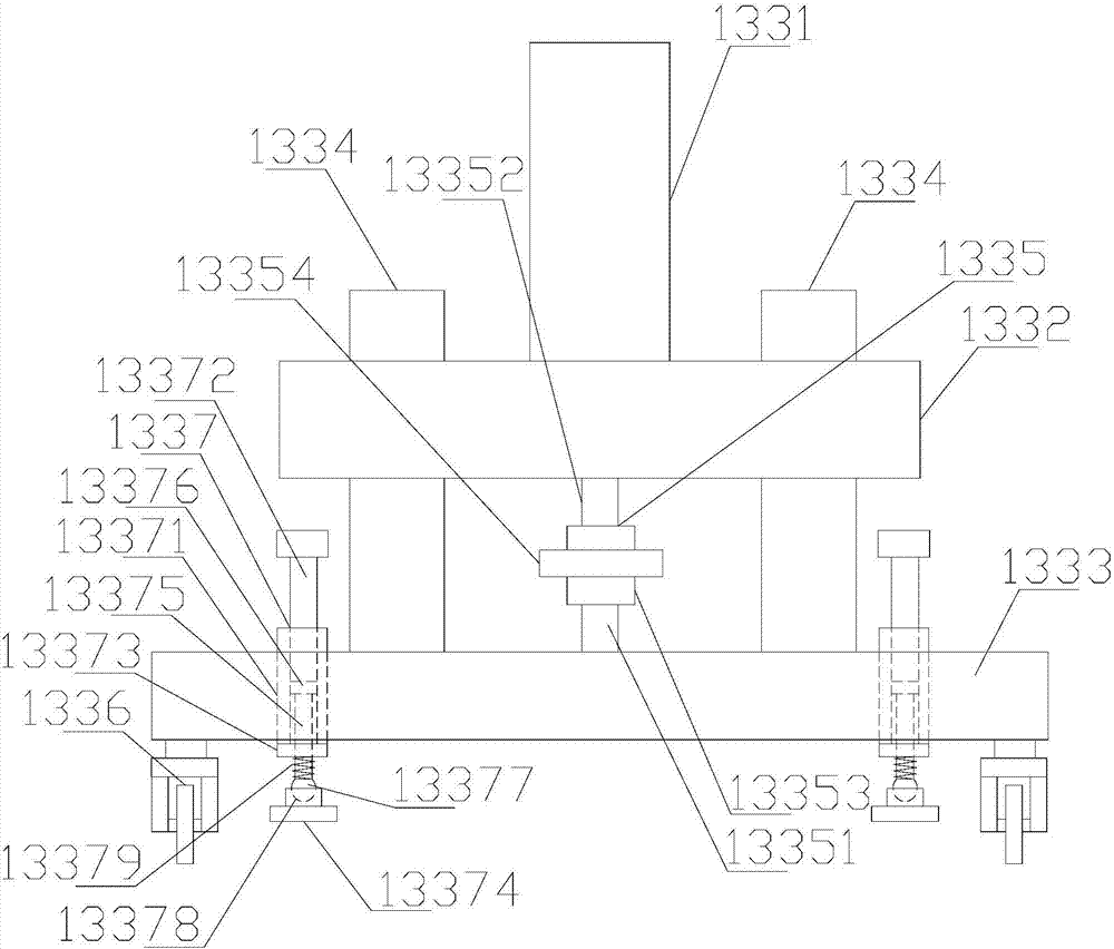
[0019] refer to figure 1 , figure 2 and image 3 , a main tapping channel of a blast furnace in the present invention includes several tapping channels 1, the tapping channels 1 include a transition channel 11, a channel body 12 and a frame body 13, and the frame body 13 is provided with a transition channel 11 and a channel body 12, the front end of the ditch body 12 communicates with the transition groove 11, the tapping groove 1 gradually decreases from front to back in a stepped manner, and the highest tapping groove among the two adjacent tapping grooves 1 The output end of 1 is located above the transition trough 11 of the lowest tap chute 1. The frame body 13 includes an installation platform 131, a girder 132 and a support mechanism 133. The bottom of the installation platform 131 is provided with a girder 132. The two ends of crossbeam 132 are all provided with support mechanism 133, and described support mechanism 133 comprises support body 1331, upper base 1332, ...


PUM


Abstract

The invention discloses a blast furnace main tapping trough, which comprises several tapping troughs, the tapping troughs include a transition groove, a ditch body and a frame body, the frame body is provided with a transition groove and a ditch body, and the ditch body The front end of the tap trough communicates with the transition trough, and the tap trough gradually decreases from front to back in a stepped manner, and the output end of the tap trough with the highest position among the two adjacent tap troughs is located at the bottom of the tap trough with the lowest position. Above the transition slot, the frame body includes a mounting platform, a girder and a supporting mechanism, the bottom of the mounting platform is provided with a girder, the two ends of the girder are provided with a supporting mechanism, and the supporting mechanism includes a supporting body, an upper base , the lower base, two positioning bodies, the adjustment mechanism and several moving wheels, compared with the prior art, it can be easily removed and installed without affecting the normal tapping, avoiding the disadvantages caused by on-site maintenance, and has strong erosion resistance and anti-corrosion High compressive strength and good wear resistance.

Description

【Technical field】 [0001] The invention relates to the technical field of ironmaking equipment, in particular to the technical field of a blast furnace main tapping trough. 【Background technique】 [0002] Blast furnace iron trough is an essential infrastructure in the blast furnace ironmaking process engineering. Its main function is to buffer the slag and iron ejected from the taphole, realize the separation of slag and iron, and further transport the slag and iron to the ladle and slag pellets respectively. chemical facilities. [0003] In the prior art, since the maintenance work must be carried out in front of the furnace, the corresponding tap hole cannot be used during the maintenance process of the tap trough, especially for small and medium-sized blast furnaces with a single tap hole. During the process, the ironmaking blast furnace must be shut down. At present, for the tapping trough, the fastest maintenance operation at present takes nearly 12 hours, and the work ...

Claims


Application Information

Patent Timeline
IPC IPC(8): C21B7/14C21B7/06C04B35/565C04B35/66
CPCC21B7/14C04B35/565C04B35/66C04B2235/3217C04B2235/3463C04B2235/349C04B2235/3873C04B2235/422C21B7/06
Inventor 俞小夏军
Owner XINCHANG SHENGXIA MACHINERY PLANT
Why Eureka
Eureka Blog
Learn More