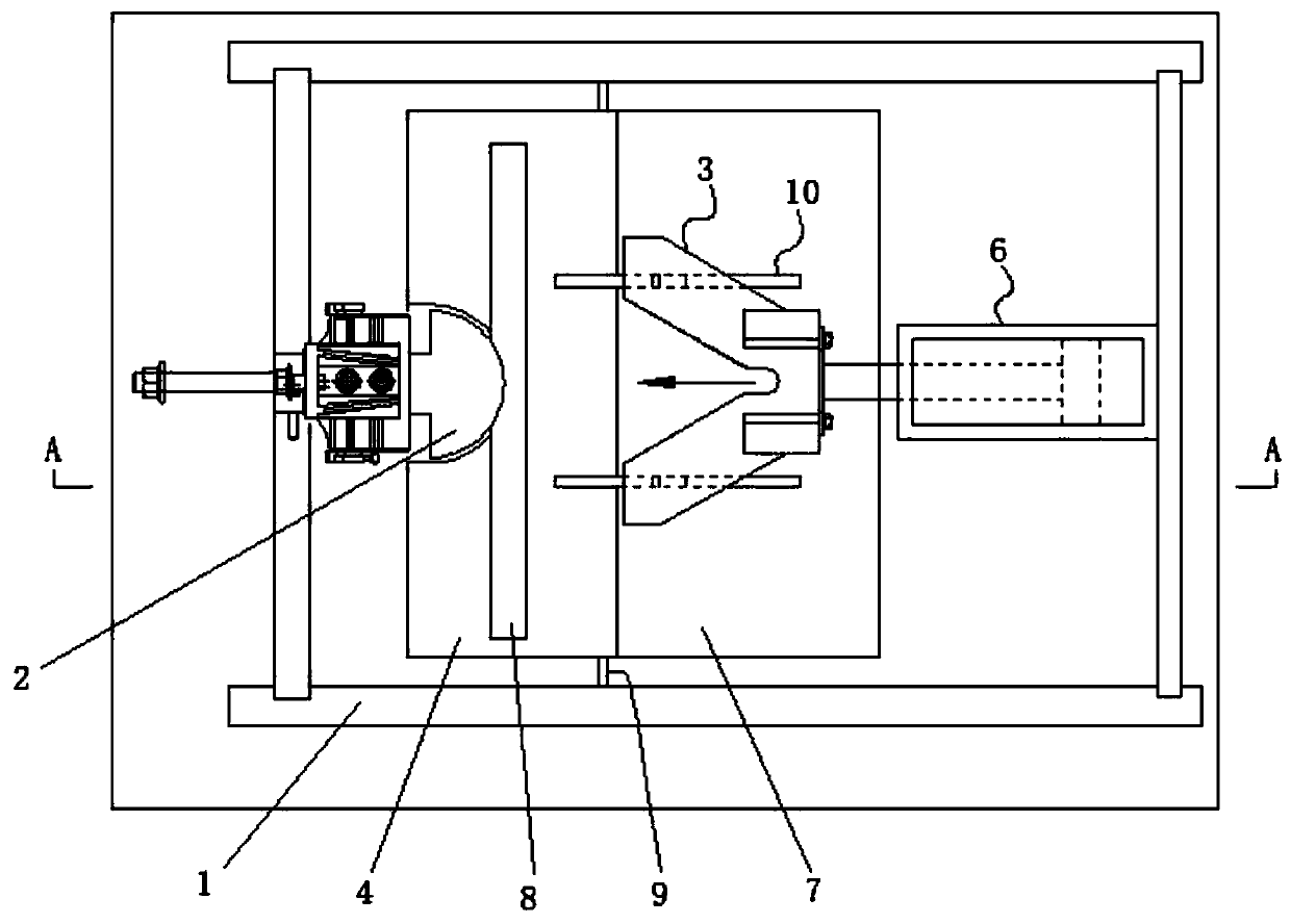
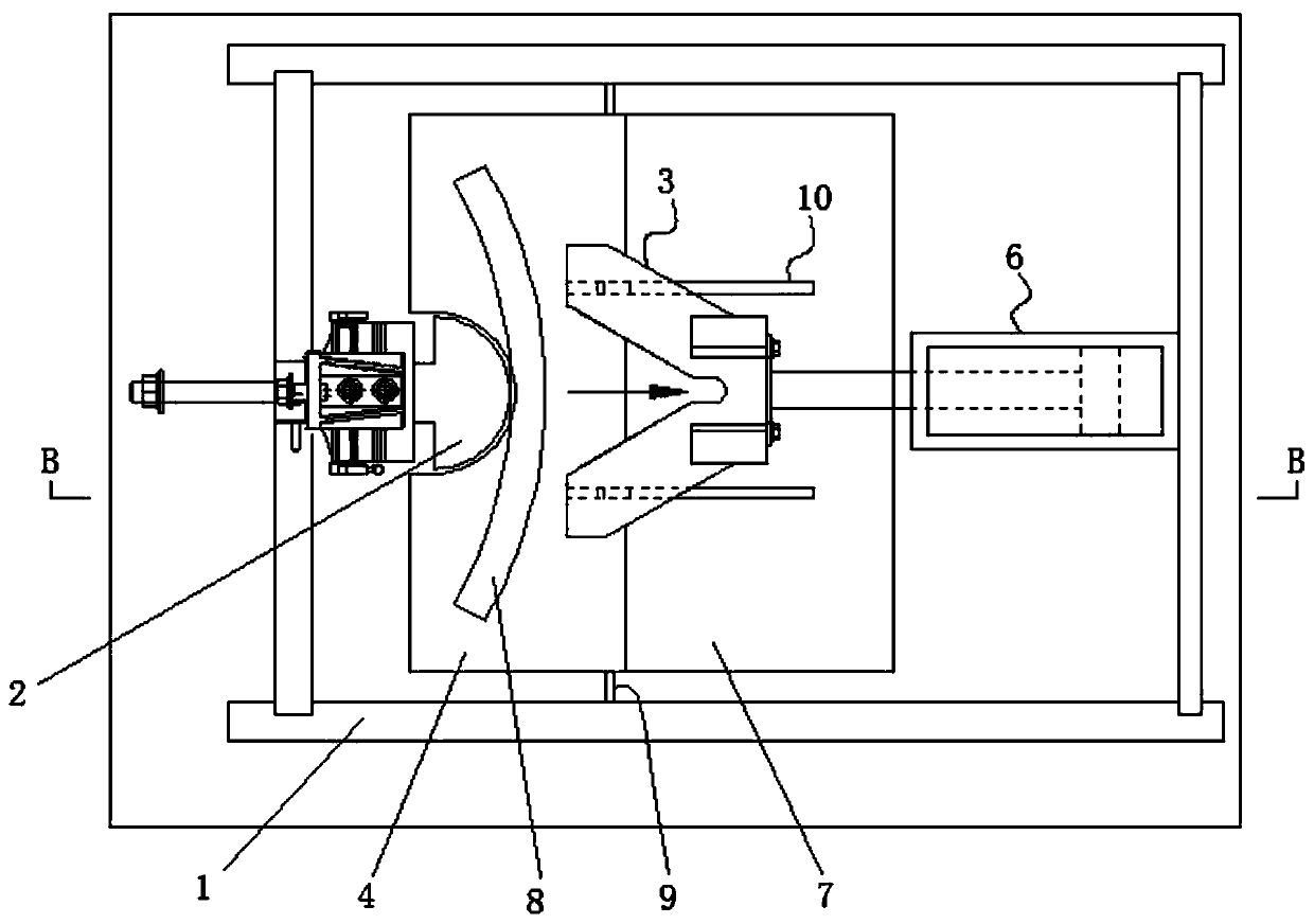
A horizontal steel pipe bending machine
A bending machine and steel pipe technology, applied in metal processing equipment, manufacturing tools, stripping devices, etc., can solve the problems of low pipe bending efficiency, inability to automatically feed and discharge materials, etc., to achieve high pipe bending efficiency and fully automatic The effect of pipe bending operation and easy operation
Active Publication Date: 2019-10-01
江苏博创升降机械有限公司
View PDF10 Cites 0 Cited by
- Summary
- Abstract
- Description
- Claims
- Application Information
AI Technical Summary
Problems solved by technology
The defect of these steel pipe bending machines is that they only have the function of bending pipes, and cannot automatically load and discharge materials, and the bending efficiency is low
Method used
View moreImage
Smart ImageViewing Examples
Examples
Embodiment 1
Login to View More PUM
 Abstract
The invention discloses a horizontal steel tube bending machine. The horizontal steel tube bending machine comprises a frame, a die, a punch, a movable plate and a linear driver, wherein the die and the linear driver are installed on the frame and are located at the same horizontal height, the punch is installed on the linear driver, and the linear driver drives the punch to do reciprocating motion relative to the die; the movable plate is arranged on the frame through a first rotating shaft, a first torsion spring is arranged on the first rotating shaft, the first torsion spring is used for maintaining the horizontal position of the movable plate, and the movable plate in the horizontal state is located between the die and the linear driver; the surface of the movable plate is used for containing a steel tube; and a rotating plate mechanism is arranged on the punch, when the linear driver drives the punch to return, the movable plate rotates through shifting of the rotating plate mechanism, and the steel tube on the movable plate slides along the inclined movable plate, so that the automatic discharging function is realized. According to the horizontal steel tube bending machine,operation workers only need to add the steel tube to the movable plate at a certain frequency when the steel tube bending machine is used, so that the operation is simpler and more convenient, and tube bending efficiency is higher.
Description
technical field The invention relates to the field of mechanical equipment, in particular to a horizontal steel pipe bending machine. Background technique Steel pipe bending machine is a kind of equipment used to bend steel pipe or round steel bar. There are many types of steel pipe bending machines in the prior art. Steel pipe bending machines generally include a die, a punch and a driver. The steel pipe is placed between the die and the punch. The driver drives the punch to squeeze the steel pipe to form a bend. The defect of these steel pipe bending machines is that they only have the function of bending pipes, and cannot automatically load and discharge materials, and the efficiency of pipe bending is low. Contents of the invention The technical problem to be solved by the present invention is to provide a steel pipe bending machine with a discharge function. The punch can not only bend the pipe but also discharge the bent pipe from the bending machine in one round t...
Claims
Login to View More Application Information
Patent Timeline
 Patent Type & Authority Patents(China)
IPC IPC(8): B21D7/06B21D45/08
Inventor 胡军赵静
Owner 江苏博创升降机械有限公司
Features
- R&D
- Intellectual Property
- Life Sciences
- Materials
- Tech Scout
- Unparalleled Data Quality
- Higher Quality Content
- 60% Fewer Hallucinations
Learn More Browse by: Latest US Patents, China's latest patents, Technical Efficacy Thesaurus, Application Domain, Technology Topic, Popular Technical Reports.
© 2025 PatSnap. All rights reserved.Legal|Privacy policy|Modern Slavery Act Transparency Statement|Sitemap|About US| Contact US: help@patsnap.com


