
Sediment impulse cleaning system of slurry pipeline

A mud pipe and sediment technology, which is applied in the field of shield tunneling, can solve the problems of large slurry discharge pipeline, high labor intensity, low work efficiency, etc., and achieve the effect of prolonging the service life

Pending Publication Date: 2018-04-24
辽宁三三工业有限公司
View PDF9 Cites 0 Cited by
  • Summary
  • Abstract
  • Description
  • Claims
  • Application Information

AI Technical Summary

Problems solved by technology

[0004] The disadvantages of the above method are: 1. The sediment tank can only be manually cleaned when the equipment is shut down, which has low work efficiency and high labor intensity; 2. Due to the large amount of slurry discharged from the slurry discharge pipeline, the sediment tank is easy to fill up , due to failure to check and clean up in time, the sediment tank is full or the mud pipeline is blocked

Method used


Image

  • Sediment impulse cleaning system of slurry pipeline
  • Sediment impulse cleaning system of slurry pipeline

Examples


Embodiment Construction

[0024] It should be noted that, in the case of no conflict, the embodiments of the present invention and the features in the embodiments can be combined with each other.

[0025] In describing the present invention, it should be understood that the terms "center", "longitudinal", "transverse", "upper", "lower", "front", "rear", "left", "right", " The orientations or positional relationships indicated by "vertical", "horizontal", "top", "bottom", "inner" and "outer" are based on the orientations or positional relationships shown in the drawings, and are only for the convenience of describing the present invention and Simplified descriptions, rather than indicating or implying that the device or element referred to must have a particular orientation, be constructed and operate in a particular orientation, and thus should not be construed as limiting the invention. In addition, the terms "first", "second", etc. are used for descriptive purposes only, and should not be understood ...


PUM


Abstract

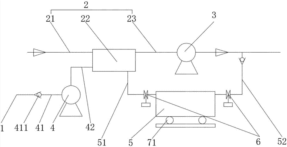
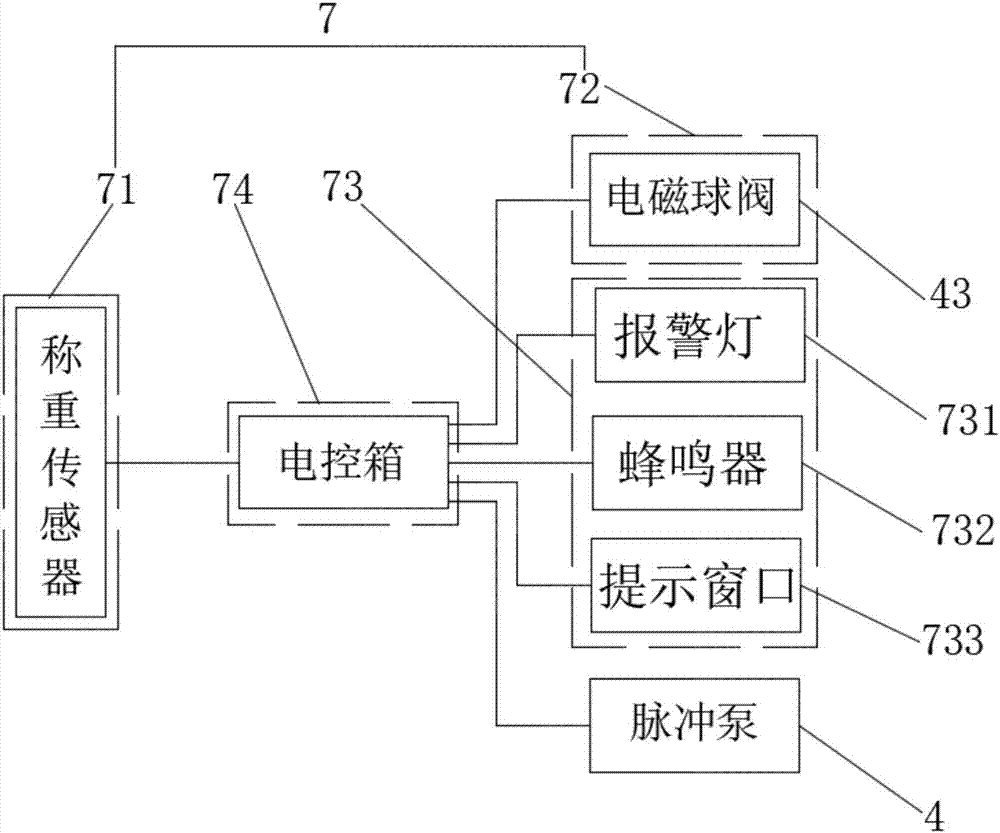
The invention provides a sediment impulse cleaning system of a slurry pipeline, which comprises a slurry feeding pipeline and a slurry discharging pipeline; the slurry discharging pipeline comprises afront end slurry discharging part, a sediment pipeline and a back end slurry discharging part which are linked in order and in series; the slurry discharging pump is mounted on the back end slurry discharging part, the slurry discharging pipeline is horizontal, and the section area of the sediment pipeline is more than the section area of the front end slurry discharging part; an impulse pump isfurther mounted between the slurry feeding pipeline and the sediment pipeline, and a fluid inlet pipe of the impulse pump is linked to the slurry feeding pipeline in series; a fluid outlet pipe of theimpulse pump is linked to the upstream of the sediment pipeline in series; the back end slurry discharging part is further linked with a sediment collecting box in parallel, and the upstream of the sediment collecting box is connected to the downstream of the sediment pipeline through a stone feeding pipe; the stone feeding pipe is located at the lower side of the back end slurry discharging part, the downstream of the sediment collecting box is linked with the downstream of the back end slurry discharging part through a recycling pipe. The cleaning system can clean the sediment box continuously without shutdown.

Description

technical field [0001] The invention belongs to the field of shield tunneling, and in particular relates to a mud pipeline sediment pulse cleaning system. Background technique [0002] Since the slurry discharge pipeline of the slurry shield machine contains a large amount of large-grained sand and gravel in the discharged slurry, the shell and impeller of the expensive slurry pump are greatly worn, which seriously affects the service life of the slurry pump. [0003] At present, the commonly used solution is to set up a sediment pipeline or a sediment box on the slurry discharge pipeline in front of the slurry pump to reduce the flow speed or sedimentation of large particles of sand before entering the slurry pump, and open the sediment box when the pump is shut down. , Take out large grains of sand and gravel. [0004] The disadvantages of the above method are: 1. The sediment tank can only be manually cleaned when the equipment is shut down, which has low work efficiency...

Claims


Application Information

Patent Timeline
Patent Type & Authority Applications(China)
IPC IPC(8): B08B9/032F04D29/70
CPCF04D29/708B08B9/0326
Inventor 刘子铭徐进
Owner 辽宁三三工业有限公司
Learn More