Eureka AIR delivers breakthrough ideas for toughest innovation challenges, trusted by R&D personnel around the world.

Load optimization method for segmented-type LED drive system

A technology for LED drive and load optimization, which is applied to lighting devices, light sources, electrical components, etc., can solve the problems of reducing the number of traversals, not being able to take into account the optimization speed and optimization effect, and achieve the effect of high efficiency

Active Publication Date: 2018-04-20
ZHEJIANG UNIV OF TECH
View PDF2 Cites 2 Cited by
  • Summary
  • Abstract
  • Description
  • Claims
  • Application Information

AI Technical Summary

Problems solved by technology

[0011] In order to overcome the shortcomings of the single traversal or average distribution method in the application of load allocation for segmented LED drive systems, that is, the optimization speed and optimization effect cannot be taken into account, the present invention provides a load optimization for segmented LED drive systems method, adopting the strategy of gradually reducing the optional range of LED load combinations and then traversing, which can not only reduce the number of traversals, but also ensure that the overall performance of the system is approximately optimal in a wide input voltage range, and realize the improvement of load optimization speed and effect

Method used


Image

  • Load optimization method for segmented-type LED drive system
  • Load optimization method for segmented-type LED drive system
  • Load optimization method for segmented-type LED drive system

Examples


Embodiment 1

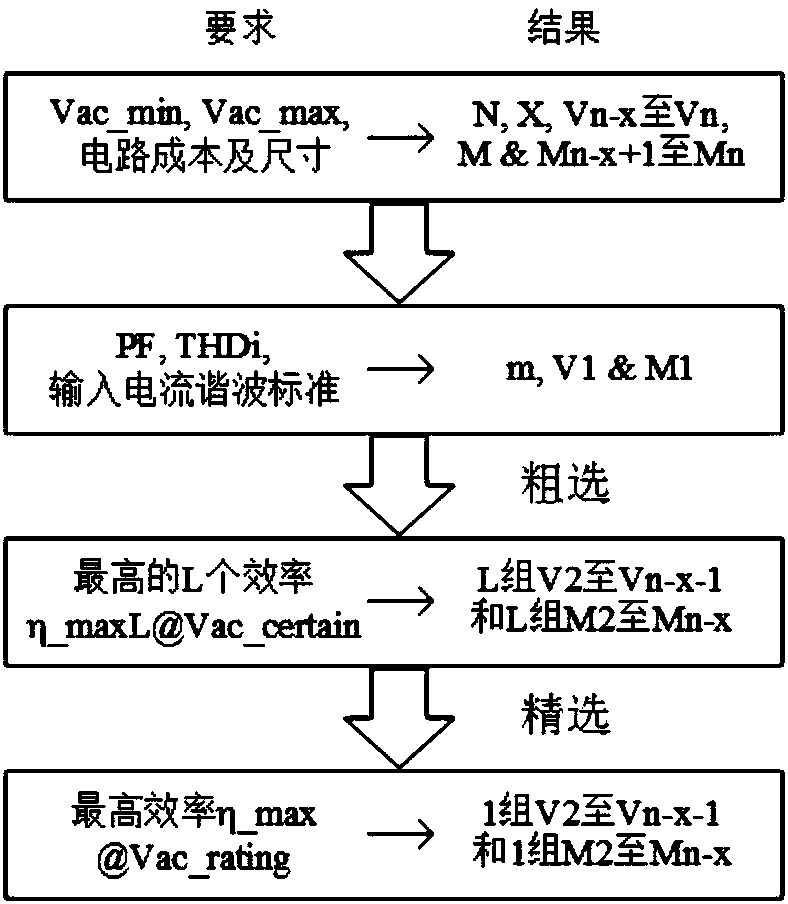
[0077] refer to Figure 3 to Figure 5 , Steps 1 to 4 of Embodiment 1 are further refined.

[0078] The processing procedure of said step 1 is:

[0079] (1.1) Determine N, X and Vn-x according to the requirements of Vac_min, Vac_max, circuit cost and size and the set ΔV;

[0080] (1.2) in to The average distribution method is used to determine Vn-x+1 to Vn within the range;

[0081] (1.3) According to VLED, calculate M and Mn-x+1 to Mn.

[0082] The processing procedure of described step 2 is:

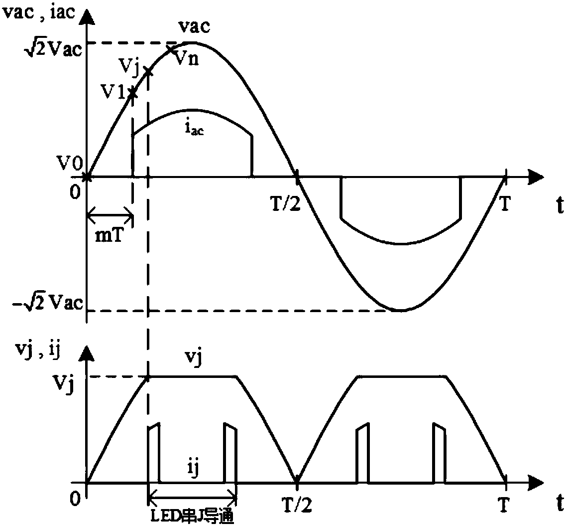
[0083] (2.1) According to f(vac) and A(ac), under the condition of Vac=Vac_certain, the method of scanning m is used to determine the upper limit m_max of m that meets the requirements of PF, THDi and input current harmonic standards;

[0084] (2.2) According to the set phase coefficient redundancy Δm, take m=m_max-Δm, and calculate V1 and M1;

[0085] (2.3) Investigate whether V1 in the range from Vac_min to Vac_max can make the input current iac meet the requirements of PF, T...

Embodiment 2

[0096] refer to image 3 , Figure 4 to Figure 9 , Steps 1 to 4 of Embodiment 1 are further refined.

[0097] The processing procedure of described step 2 is:

[0098] (2.1) According to f(vac) and A(ac), within the range of Vac_min to Vac_max, the method of scanning m is used to determine the upper limit m_max of m that meets the requirements of PF, THDi and input current harmonic standards;

[0099] (2.2) According to the set phase coefficient redundancy Δm, take m=m_max-Δm, and calculate V1 and M1.

[0100] Except for step 2, other steps of this embodiment are the same as those of embodiment 1, and the optimization effect is also similar to that of embodiment 1.


PUM


Abstract

The invention discloses a load optimization method for a segmented-type LED drive system, and the method comprises the optimization process of LED load combinations M1 to Mn at four steps. The methodemploys a strategy that the selectable range of the LED load combinations is reduced step by step firstly and then the traversal is carried out, thereby reducing the number of traversal times, guaranteeing that the comprehensive performances of a system in a wide input voltage range are approximately optimal, and achieving the improvement of the load optimization speed and effect. A load optimization result can enable the segmented-type LED drive system working in the wide input voltage range to achieve the highest efficiency under the condition that the circuit cost, size, PF, THDi and inputcurrent harmonic standard are met.

Description

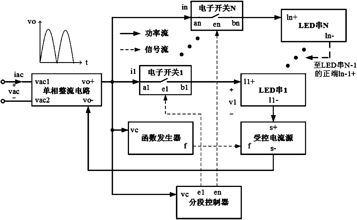
technical field [0001] The invention relates to a load optimization method, which is mainly oriented to a segmented LED driving system with a wide input voltage range. Background technique [0002] Such as figure 1 As shown, a common segmented LED drive system consists of a single-phase rectifier circuit, electronic switch 1 to electronic switch N, function generator, segmental controller, controlled current source, LED string 1 to LED string N. The input voltage vac and output voltage of the single-phase rectifier circuit satisfy Vac is the effective value of vac, and T is the period. The segment controller determines the connection state of LED string 1 to LED string N according to the value of vo, and its ports e1 to en control the on-off state of electronic switch 1 to electronic switch N respectively. The function generator is the control source of the controlled current source, which generates the envelope function f(vac) of the input current iac of the single-phas...

Claims


Application Information

Patent Timeline
Patent Type & Authority Applications(China)
IPC IPC(8): H05B33/08H05B44/00
CPCH05B45/48H05B45/50
Inventor 陈怡
Owner ZHEJIANG UNIV OF TECH
Why Eureka
Eureka Blog
Learn More