A defocus-based non-uniform correction analysis method for infrared imaging system

An infrared imaging system and non-uniform correction technology, which is applied in the field of optical simulation, can solve the problems of large temperature difference between the correction screen and the actual environment, and the large temperature difference between the baffle temperature and the outside world, so as to improve the ability of target discovery and recognition, and the actual effect is remarkable. good authenticity

Active Publication Date: 2020-02-14
LUOYANG INST OF ELECTRO OPTICAL EQUIP OF AVIC
View PDF21 Cites 0 Cited by
  • Summary
  • Abstract
  • Description
  • Claims
  • Application Information

AI Technical Summary

Problems solved by technology

The most commonly used method is to add a baffle correction mechanism in the design of the infrared imaging system, and use the baffle to cut off the optical path transmission and perform image correction. However, when the infrared system works in a relatively harsh temperature condition, the temperature difference between the baffle and the outside temperature is large , resulting in a large temperature difference between the calibration screen and the actual environment

Method used


Image

  • A defocus-based non-uniform correction analysis method for infrared imaging system

Examples


Embodiment Construction

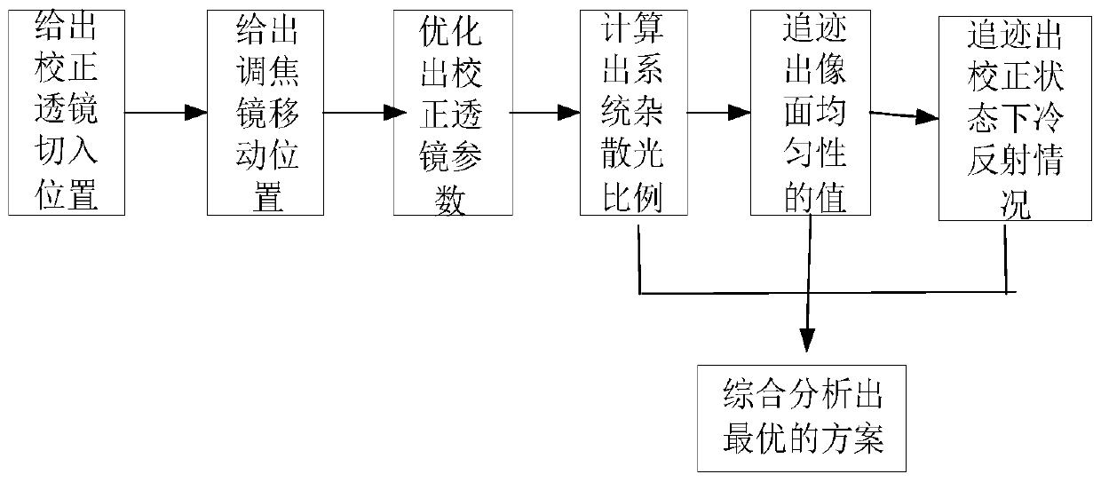
[0021] Now in conjunction with embodiment, accompanying drawing, the present invention will be further described:

[0022] Step 1: Place the correction lens between convergence one and convergence two in the continuous focusing infrared imaging system; the material of the correction lens is germanium, and the cut-in position of the correction lens is: the distance from the rear surface of the correction lens to the front surface of the convergence lens 2 7.62mm;

[0023] Step 2: In the optical simulation software, the uniformity of the focal plane of the continuous focusing infrared imaging system is used as a constraint condition, and the moving position of the focusing mirror is used as a variable, and the least square method is used to automatically optimize, and all the focusing conditions that meet the constraints are obtained. The shift position of the focal lens is described;

[0024] Step 3: In the optical simulation software, the uniformity of the focal plane of the ...


PUM


Abstract

The invention relates to a non-uniform correction analysis method for an infrared imaging system based on defocusing. By moving a focusing mirror or adding a defocusing lens to change the optical path of the infrared imaging system, the original imaging optical path is defocused and then on the focal plane of the detector. A relatively uniform light intensity distribution is formed, and at the same time, stray light and cold reflection are not introduced into the system during the defocusing process, and finally the infrared imaging system can achieve the purpose of non-uniform correction without a baffle. The analysis method provides three defocus correction methods: focus lens movement correction, insertion lens correction, and combination of focus lens movement and insertion lens, and introduces image plane uniformity, system stray light and narcissus intensity into the analysis of non-uniform correction As an evaluation factor, each evaluation factor can be quantitatively analyzed, which improves the accuracy of the analysis. At the same time, the defocus correction can correct the scene information into the system in practical application, which improves the target discovery and recognition ability of the infrared imaging system.

Description

technical field [0001] The invention belongs to the field of optical simulation, and relates to a non-uniform correction analysis method for an infrared imaging system based on defocus. Background technique [0002] Due to the limitations of the existing manufacturing process level and materials, the response characteristics of each detection unit of the infrared focal plane array are not completely consistent, and it is superimposed on the image in the form of fixed pattern noise, which is the non-uniformity of the infrared focal plane array. It seriously affects the imaging quality of the infrared system, making it difficult to distinguish the target image from the background, which limits the performance of the infrared focal plane array and also limits its military and civilian applications. [0003] In order to solve the above problems, the first is to improve the development and production level of infrared focal plane array devices, and further reduce the non-uniformi...

Claims


Application Information

Patent Timeline
Patent Type & Authority Patents(China)
IPC IPC(8): G02B27/00G01J5/08
CPCG02B27/0025G02B27/0068G01J5/0806G01J2005/0077G01J5/80
Inventor 任国栋赵菲菲赵延张良
Owner LUOYANG INST OF ELECTRO OPTICAL EQUIP OF AVIC
Why Eureka
Try Eureka