
Diffracted wave field extraction method and device

An extraction method and diffraction wave technology, applied in the field of diffraction wave field extraction, can solve the problems of poor precision of diffraction waves

Active Publication Date: 2018-04-20
CHINA UNIV OF MINING & TECH (BEIJING)
View PDF5 Cites 7 Cited by
  • Summary
  • Abstract
  • Description
  • Claims
  • Application Information

AI Technical Summary

Problems solved by technology

[0004] In view of this, the object of the present invention is to provide a diffraction wave field extraction method and device to alleviate the technical problem of poor precision of the diffraction wave extracted by the traditional diffraction wave extraction method

Method used


Image

  • Diffracted wave field extraction method and device
  • Diffracted wave field extraction method and device
  • Diffracted wave field extraction method and device

Examples


Embodiment 1

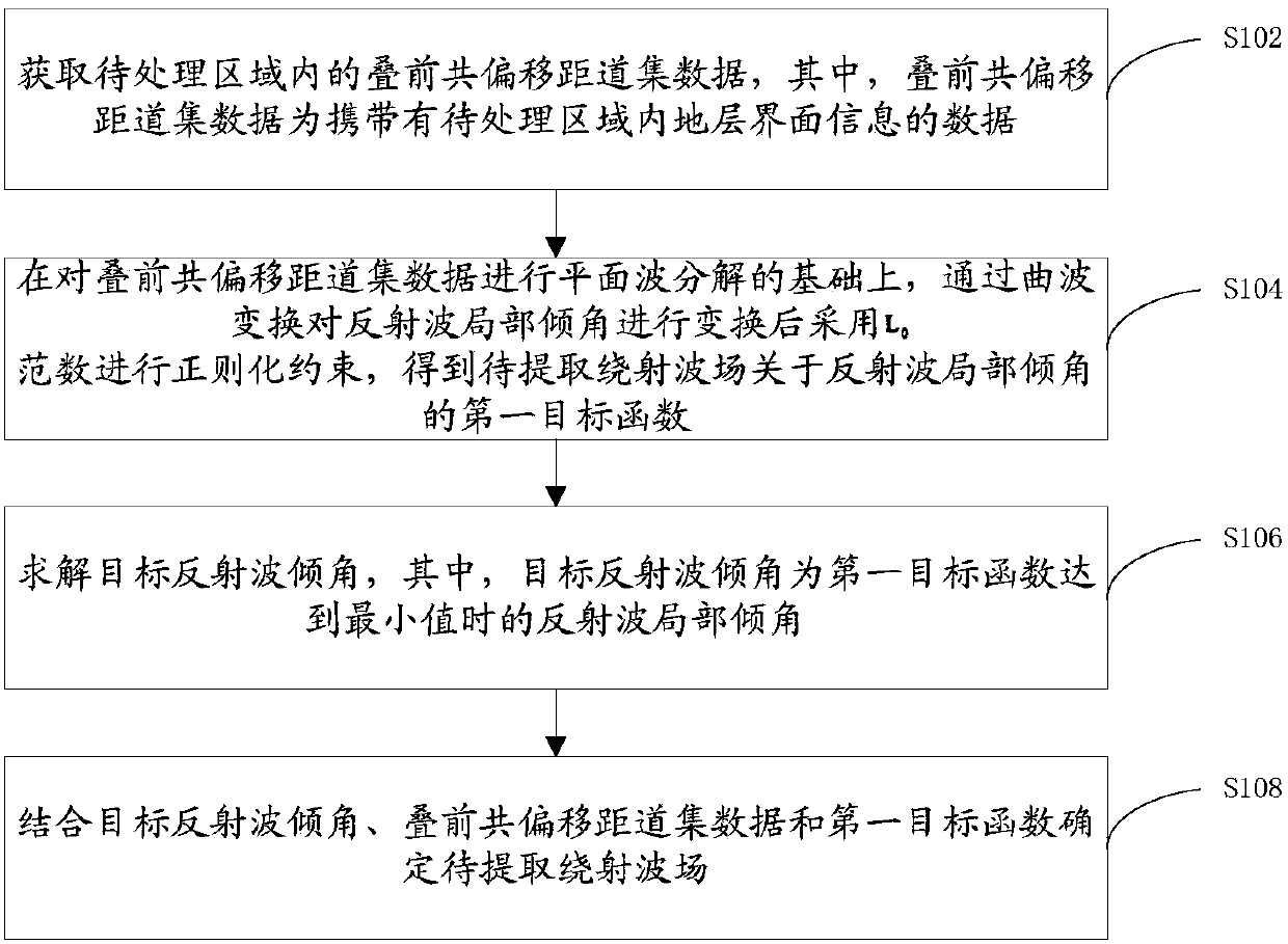
[0042] A method for extracting a diffracted wave field provided by an embodiment of the present invention, such as figure 1 shown, including:

[0043] Step S102, acquiring pre-stack common-offset gather data in the area to be processed, wherein the pre-stack common-offset gather data is data carrying formation interface information in the area to be processed.

[0044] In the embodiment of the present invention, the common-offset seismic gather data is the seismic wave detected by the acquisition unit. The specific process is: artificially excite the seismic wave at the shot point, the seismic wave propagates in all directions, and when encountering different underground rocks Reflected waves and diffracted waves are generated when the surface is decomposed, and these reflected waves and diffracted waves return to the ground to cause ground vibrations, and then the acquisition unit is set along the equidistant distance from the shot point to detect the seismic waves that cause...

Embodiment 2

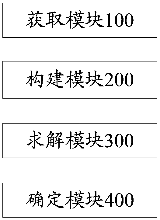
[0087] Such as Figure 3 to Figure 4 As shown, the embodiment of the present invention provides a diffracted wave field extraction device.

[0088] see image 3 , the diffraction wave field extraction device includes:

[0089] An acquisition module 100, configured to acquire pre-stack common-offset gather data in the area to be processed, wherein the pre-stack common-offset gather data is data that carries formation interface information in the area to be processed;

[0090] The building block 200 is used for performing plane wave decomposition on the pre-stack common offset gather data, transforming the local inclination angle of the reflected wave through the curvelet transform and adopting L 0 The norm is regularized and constrained to obtain the first objective function of the local dip angle of the diffracted wave field to be extracted with respect to the reflected wave;

[0091] The solving module 300 is used to solve the inclination angle of the target reflected wave...


PUM


Abstract

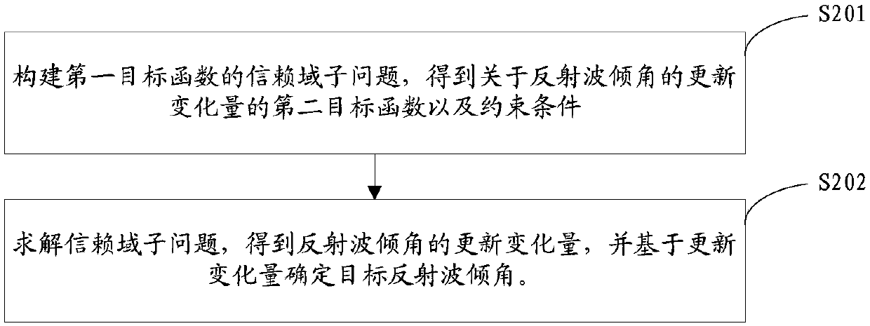
The invention provides a diffracted wave field extraction method and device, and relates to the technical field of diffraction field extraction. The method includes: obtaining a pre-stack common-offset gather data in an area to be processed, wherein the pre-stack common-offset gather data carries the stratum interface information in the area to be processed; on the basis of plane wave decomposition on the pre-stack common-offset gather data, transforming the local dip angle of a reflected wave by curvelet transform and then performing regular constraint by using the L0 norm so as to obtain thefirst objective function of the diffracted wave field to be extracted relative to the local dip angle of the reflected wave; and solving the target reflection wave dip angle by a trust region algorithm, wherein the target reflection wave dip angle is the reflection wave dip angle when the first objective function reaches the minimum; and determining the diffraction wave field to be extracted by combining the target reflected wave dip angle, the pre-stack common-offset gather data and the first objective function. The method and device alleviate a technical problem that the diffraction wave extracted by the traditional diffraction wave extraction method is poor in accuracy.

Description

technical field [0001] The present invention relates to the technical field of diffraction wave field extraction, in particular to a diffraction wave field extraction method and device. Background technique [0002] Conventional seismic exploration technology is based on the reflection wave theory. When the seismic wave propagates in the underground space, when it encounters the lithological interface, according to Snell’s law, the reflection wave is generated and received by the surface geophone, so the reflection wave carries a large Scale geological body information can describe the stratigraphic structure and trend in detail. At the same time, due to the interaction of in-situ stress between formations, there are still small-scale geological bodies such as faults and cracks in the underground space. The reflected wave theory can no longer accurately describe small-scale geological bodies. Therefore, the exploration of small-scale geological bodies is very important. ...

Claims


Application Information

Patent Timeline
Patent Type & Authority Applications(China)
IPC IPC(8): G01V1/28
CPCG01V1/28
Inventor 林朋彭苏萍赵惊涛杜文凤崔晓芹
Owner CHINA UNIV OF MINING & TECH (BEIJING)
Learn More