Electronic steering column lock and manufacturing process of shell of electronic steering column lock

A steering tube and housing technology is applied in the field of the production process of an electronic steering column lock and its housing. The effect of low tolerance requirements

Active Publication Date: 2018-04-20
杭州国威科技有限公司
View PDF14 Cites 6 Cited by
  • Summary
  • Abstract
  • Description
  • Claims
  • Application Information

AI Technical Summary

Problems solved by technology

[0003] The shell and base of the existing electronic steering column lock are connected by anti-theft bolts to prevent theft. Can be easily opened, so not safe
[0004]The existing electronic steering column lock requires high tolerance precision of components, troublesome manufacture and complicated assembly process
The detection switch inside the existing electronic steering column lock is very close to the base, so the circuit is prone to failure, and the production and installation are complicated
[0005]The shell of the existing electronic steering column lock needs many processes to complete the production, the production efficiency is low, and the labor cost is high
[0006]The control system chip of the existing electronic steering column lock has low integration level, slow production, high scrap rate and high failure rate
Once the control system of the electronic steering column lock fails, it will cause serious safety hazards to the driver

Method used


Image

  • Electronic steering column lock and manufacturing process of shell of electronic steering column lock
  • Electronic steering column lock and manufacturing process of shell of electronic steering column lock
  • Electronic steering column lock and manufacturing process of shell of electronic steering column lock

Examples


Embodiment Construction

[0019] The specific implementation manners of the present invention will be further described in detail below in conjunction with the accompanying drawings and embodiments. The following examples are used to illustrate the present invention, but are not intended to limit the scope of the present invention.

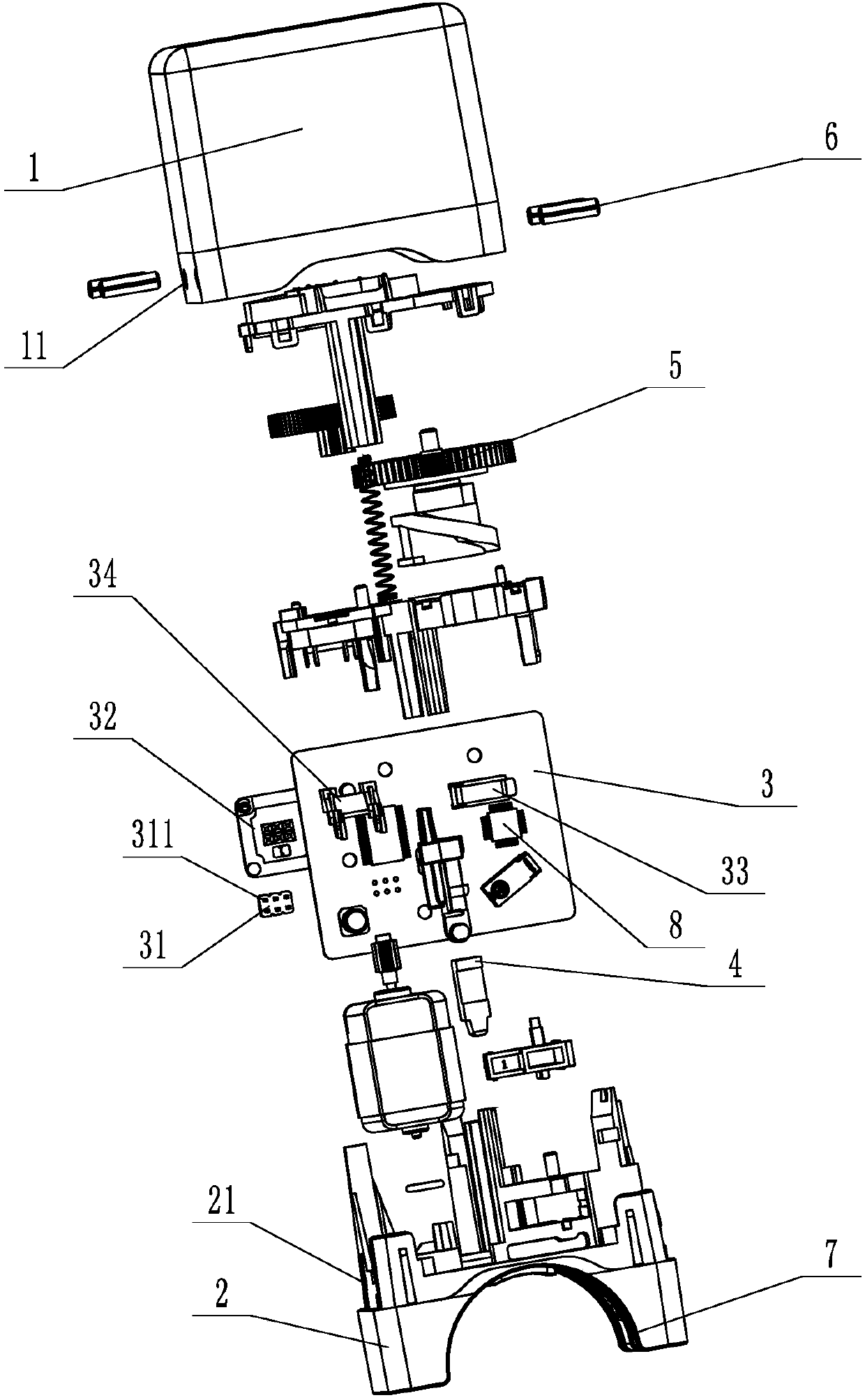
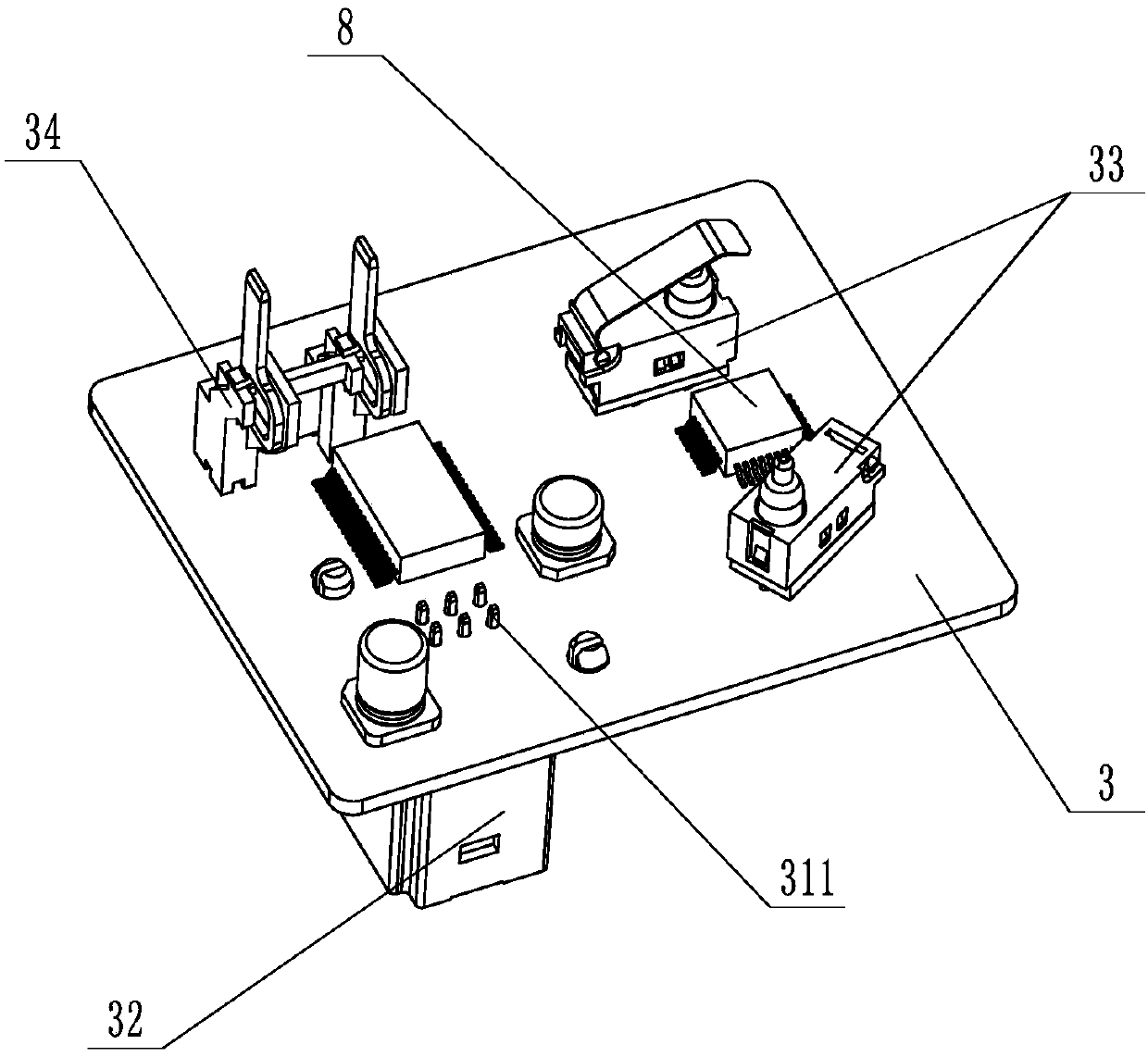
[0020] Such as Figure 1 to Figure 3 An electronic steering column lock shown includes a housing 1, a base 2 matched with the housing 1, a circuit board 3 arranged in the housing 1, a control system 8, connecting elements, a locking device 4 and a driving The locking device 4 is used to lock the driving device 5, the two opposite side walls of the housing 1 are provided with through holes 11, and the base 2 is provided with a counterbore 21 at a position corresponding to the through holes 11. The through hole 11 is connected to the counterbore 21 through the elastic pin 6, and the housing 1 and the base 2 are connected by riveting through the elastic pin 6. The connecting...


PUM


Abstract

The invention provides an electronic steering column lock, comprising a shell, a base matched with the shell, a circuit board, a connecting element, a locking device arranged in the shell, and a driving device for driving the locking device to perform locking. Through holes are formed in the two opposite side walls of the shell. Counterbores are formed in the positions, corresponding to the through holes, of the base. The through holes are connected with the counterbores through elastic pins. The shell and the base are riveted and connected by the elastic pins. The connecting element comprisesa terminal block arranged on the circuit board and a terminal block shell sleeved on the terminal block. The terminal block is provided with pins for matching with the circuit board in an insertion manner. The pins are inserted into the circuit board and then fixed by welding. The connecting element further comprises a detection switch and a power supply terminal arranged on the side, opposite tothe terminal block, of the circuit board. The detection switch is inclined relative to the length direction of the circuit board.

Description

technical field [0001] The invention relates to a manufacturing process of an electronic steering column lock and its shell. Background technique [0002] The electronic steering column lock is a new product that replaces the traditional mechanical steering column lock, and it is mainly used with the smart key system or the keyless start system. In the parking state, the locking device will automatically lock the steering column to ensure that the steering wheel will not turn; and the steering wheel will be unlocked before the engine is started, and it needs to be kept unlocked during the entire driving process. The existing locking device comprises a dead bolt, a dead bolt spring, a dead bolt connecting rod and a safety bolt. [0003] The shell and base of the existing electronic steering column lock are connected by anti-theft bolts to play an anti-theft effect, but this connection method can be easily opened as long as a suitable tool is used, so it is not safe. [0004...

Claims


Application Information

Patent Timeline
IPC IPC(8): B60R25/0215B23P15/00H05K7/20
CPCH05K7/209B23P15/00B60R25/0215
Inventor 周建军林严海赖崇鹏陈志兴
Owner 杭州国威科技有限公司
Why Eureka
Try Eureka