Integrated mounting structure of electric vehicle driving system

A technology of drive system and installation structure, applied in electric power unit, power unit, control unit, etc., can solve the problem of unfavorable three-in-one structure installation and maintenance, front cabin beam routing, complicated pipeline, and scattered drive system installation structure. and other problems, to achieve the effect of good shock absorption, convenient layout, and improved integration.

Inactive Publication Date: 2018-04-20
ZHIDOU ELECTRIC VEHICLE CO LTD
View PDF8 Cites 2 Cited by
  • Summary
  • Abstract
  • Description
  • Claims
  • Application Information

AI Technical Summary

Problems solved by technology

However, the existing automobile drive system generally uses an independent motor controller and motor. The motor controller is arranged on the beam of the front cabin, and the motor and the reducer are matched and arranged on the body through suspension. Drive system installation structure. The disadvantage of this structure is that the front cabin takes up a lot of space. For A00 class cars, the three-in-one junction box, DC-DC, OBC and motor controller are arranged in layers on the front cabin beam. Conducive to the installation and maintenance of the three-in-one structure; the wiring and piping of the front cabin beam are relatively complicated, and the results of the collision safety test are poor
However, this invention cannot overcome a series of problems such as scattered installation structure of the drive system, large space occupied by the front cabin, and poor crash test results of the whole vehicle.

Method used


Image

  • Integrated mounting structure of electric vehicle driving system
  • Integrated mounting structure of electric vehicle driving system
  • Integrated mounting structure of electric vehicle driving system

Examples


Embodiment 1

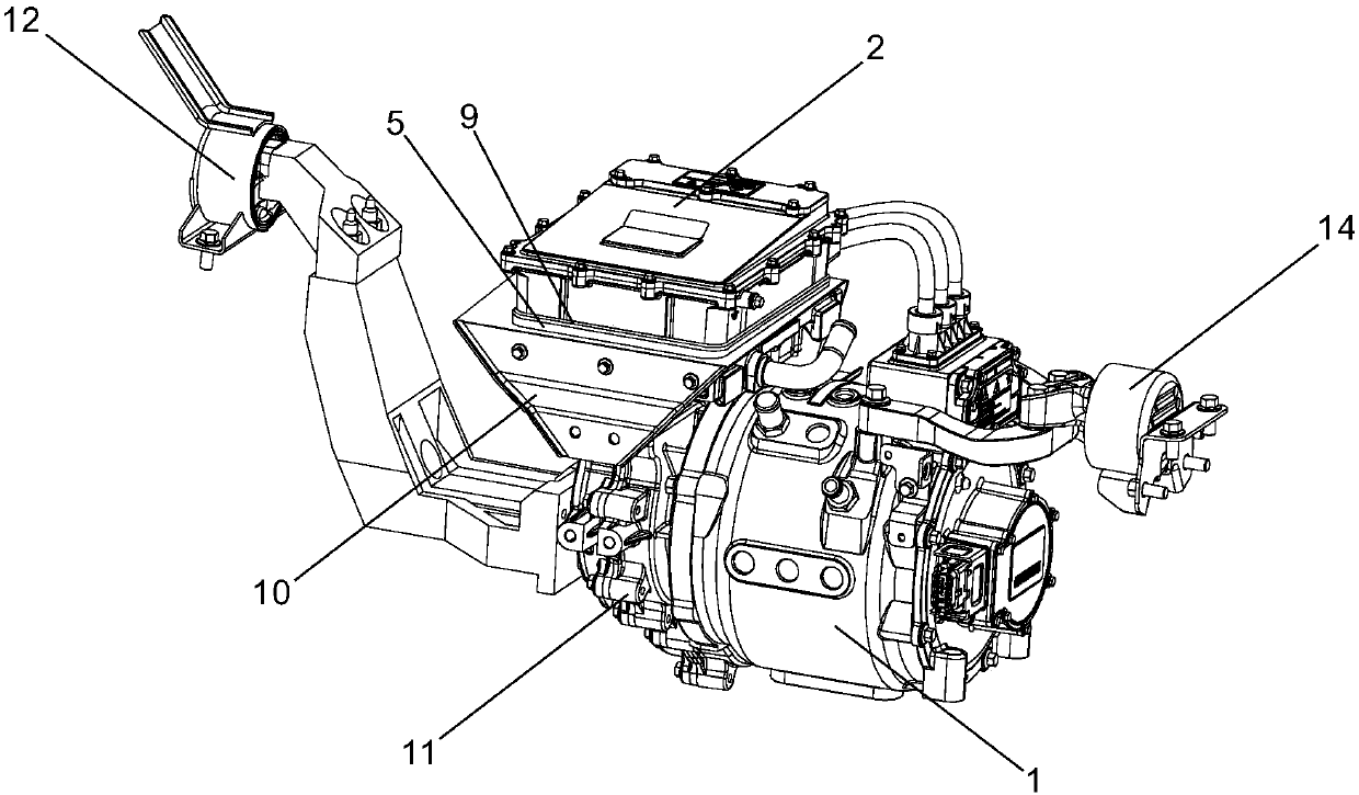
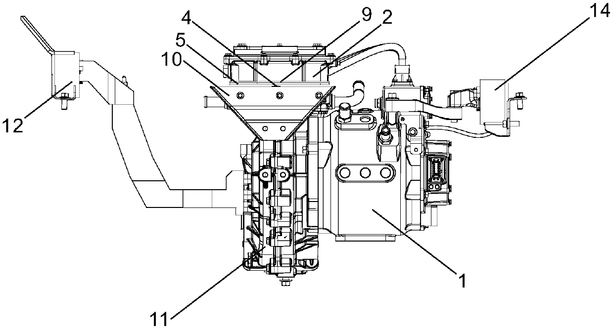
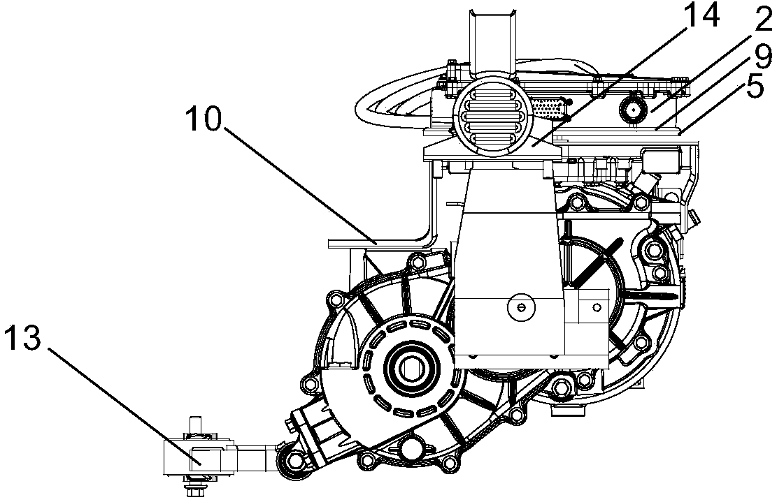
[0026] Such as Figure 1 to Figure 4As shown, an electric vehicle drive system integrated installation structure includes a motor 1 and a motor controller 2. A controller bracket 10 is installed on the motor 1 shell through bolts. The controller bracket 10 includes an integrally bent support plate and a fixed Feet, the fixed feet are located at both ends of the support plate, one end of the fixed foot is a vertical flat plate, fixed to the side of the motor 1 by bolts, the other end of the fixed foot is L-shaped, fixed to the top of the motor 1 by bolts, and the fixed feet support the controller bracket 10 The plate is suspended in the air, the support plate is provided with internal threads, and a shock absorber 3 is fixed on the support plate. The shock absorber 3 is a fluid buffer filled with nitrogen gas. The outer circumference of the shock absorber 3 is provided with threads. It is connected with the controller bracket by thread. The motor controller 2 is fixedly connec...

Embodiment 2

[0029] Such as Figure 5 As shown, the shock absorber 3 is a fluid buffer filled with hydraulic oil, and there are four shock absorbers 3 distributed on the four corners of the bottom surface of the tray 5. The buffer member 7 is a V-shaped spring piece, and the two ends of the spring piece They are respectively abutted against the side of the controller liner 6 and the side blocking wall 8 . All the other are with embodiment 1.

Embodiment 3

[0031] Such as Figure 6 , Figure 7 As shown, the shock absorbers are four rubber shock absorbers. The top and bottom ends of the rubber shock absorbers are each provided with a connecting column 15 with an external thread, and the connecting column 15 on the top of the rubber shock absorber is threaded with the controller bracket 10. Connect, the motor controller 2 is then threaded on the connecting column 15 at the top of the rubber shock absorber. All the other are with embodiment 1.


PUM


Abstract

The invention discloses an integrated mounting structure of an electric vehicle driving system. The structure comprises a motor and a motor controller, wherein the motor controller is mounted on the motor through a controller bracket, a damper is fixedly arranged on the controller bracket, and the motor controller is fixedly connected to the damper. The structure disclosed by the invention has theadvantages that the layout of the electric vehicle driving system is optimized, and the motor controller is arranged on a power assembly, so that the arrangement space of a fore-cabin can be saved, routing pipelines in the fore-cabin can be arranged more conveniently and reasonably, and more space is provided for strengthening the structure, thereby improving the collision safety coefficient of the head of a vehicle; and by adopting the measure of performing comprehensive damping in a normal direction and a tangential direction through the damper or the combination of the damper and a buffercomponent, the connecting structure between the motor controller and the motor can be effectively avoided from being loosened by vibration, and electronic components and circuits in the motor controller can be prevented from being damaged and deactivated, disconnected and the like due to vibration.

Description

technical field [0001] The invention relates to an installation structure of an automobile drive system, more specifically, it relates to an integrated installation structure of an electric automobile drive system. Background technique [0002] At present, some cities in China are vigorously promoting the traffic mode of car sharing in order to alleviate problems such as traffic jams, parking occupation of public space, and air pollution. Small and micro electric vehicles are ideal vehicles for this mode. The space is relatively small, how to reasonably arrange the car drive system in a small space and meet certain crash test standards has become a problem that car manufacturers need to face and work hard to solve. However, the existing automobile drive system generally adopts an independent motor controller and motor. The motor controller is arranged on the beam of the front cabin, and the motor and the reducer are matched and arranged on the body through suspension. This i...

Claims


Application Information

Patent Timeline
Patent Type & Authority Applications(China)
IPC IPC(8): B60K1/00B60K17/06F16F15/023
Inventor 王震鲍文光闫优胜樊晓浒何志刚
Owner ZHIDOU ELECTRIC VEHICLE CO LTD
Why Eureka
Try Eureka