
Spiral flow drainage device for ground natural gas transportation pipeline

A technology for transportation pipelines and drainage devices, which is applied in the direction of pipe components, pipes/pipe joints/pipe fittings, mechanical equipment, etc., can solve the problems of affecting natural gas transmission efficiency, pipeline corrosion, affecting pipelines, etc., to improve the flow rate and increase the impact force. and spiral flow intensity to ensure the effect of gas transmission efficiency

Active Publication Date: 2018-04-17
CHANGZHOU UNIV
View PDF7 Cites 1 Cited by
  • Summary
  • Abstract
  • Description
  • Claims
  • Application Information

AI Technical Summary

Problems solved by technology

[0005] The purpose of the present invention is to aim at the current process of using pipelines to transport natural gas. Due to the heat exchange between the pipe wall and the surrounding environment, the condensate may be precipitated. The low-lying or undulating sections of the pipeline produce liquid accumulation, which affects the gas transmission efficiency of natural gas, and will cause corrosion to the pipeline and other safety issues that affect the safe transportation of the pipeline. A new type of pipeline liquid-carrying technology was invented.
The technical problem to be solved is that liquid accumulation often occurs in low-lying or undulating sections of surface natural gas gathering and transportation pipelines, and there is currently no efficient method for carrying liquid accumulation, so after fully considering various pipeline liquid carrying methods, provide A new pipeline spiral flow drainage device with high efficiency of pipeline liquid carrying efficiency, no pipeline jamming and no influence on the actual operation of natural gas pipelines

Method used


Image

  • Spiral flow drainage device for ground natural gas transportation pipeline
  • Spiral flow drainage device for ground natural gas transportation pipeline
  • Spiral flow drainage device for ground natural gas transportation pipeline

Examples


Embodiment Construction

[0023] Below in conjunction with accompanying drawing and specific embodiment, content of the present invention is described in further detail, and promptly is the specific parameter of a set of device below:

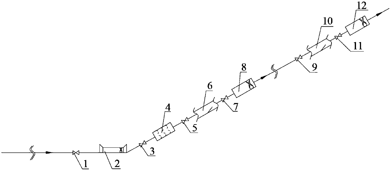
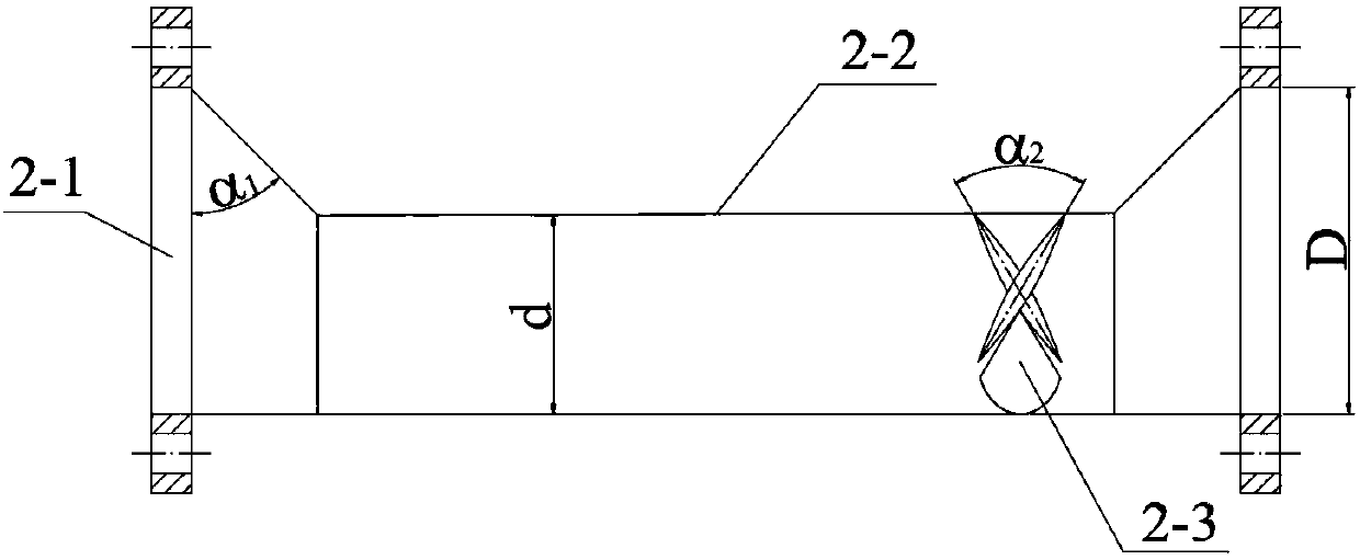
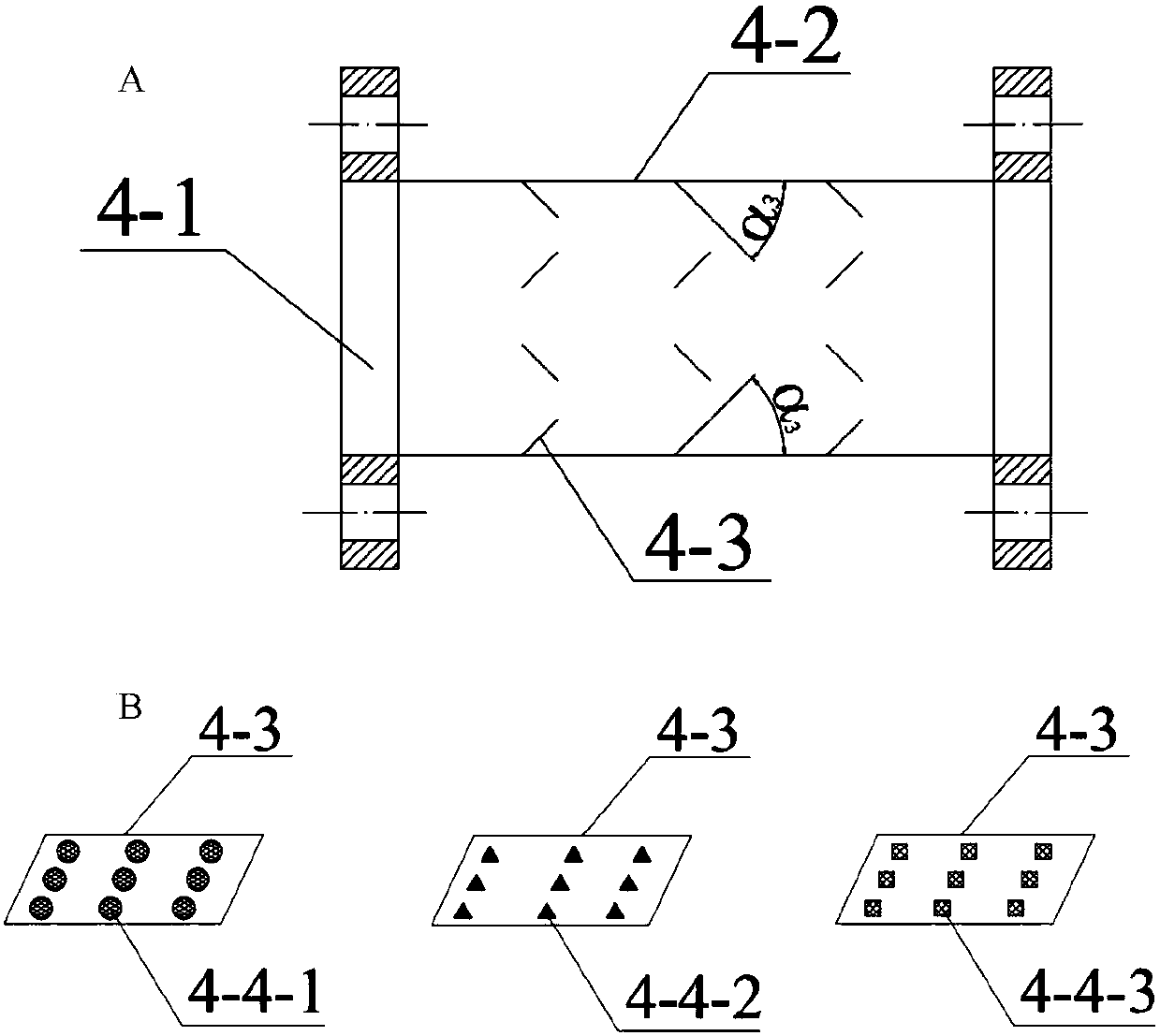
[0024]The invention comprises a liquid accumulation starting device, a spiral generating device, a liquid drop generating device and a liquid accumulation intercepting device. The liquid effusion starting device mainly includes a one-way valve (1), and the liquid lifting device (2) is composed of a flange (2-1), a variable diameter pipe (2-2), and a blade (2-3), and one end is composed of One-way valve (1) links to each other, and the other end links to each other with one-way valve (3); Described droplet generation device (4) comprises flange (4-1), pipeline (4-2) and droplet generation sheet ( 4-3) and the broken liquid hole (4-4) thereon, one end is connected with the one-way valve (3), and the other end is connected with the one-way valve (5); The cut-off piece (6-...


PUM


Abstract

The invention discloses a spiral flow drainage device for a ground natural gas transportation pipeline and relates to the field of the petroleum and natural gas industry. The spiral flow drainage device comprises an accumulated liquid starting device, a spiral generating device, a liquid drop generating device and an accumulated liquid intercepting device. The accumulated liquid starting device isadopted, through the mode that a variable diameter pipe and the spiral flow generating device are combined, the flow speed is increased, impact force is increased, and spiral flow strength is improved, so that a gas flow impacts accumulated liquid at the low-lying position or the corner of the pipeline, the accumulated liquid is rolled up and carried through combination of a spiral flow and the impact force, and thus the accumulated liquid in the pipeline is effectively removed.

Description

technical field [0001] The invention relates to the field of petroleum and natural gas industry, in particular to a spiral flow drainage device used in actual natural gas pipelines. Background technique [0002] Today, when the world's energy is increasingly tense, natural gas with the characteristics of cleanness, safety, and high calorific value is favored by various countries. At present, pipeline transportation is the main mode of natural gas transportation, but in the process of pipeline transportation, due to the heat exchange between the pipe wall and the surrounding environment, condensate may be precipitated. At the same time, with the development of the gas field, the gas field will Water comes out, causing fluid to build up in the lines. The generation of pipeline effusion will cause the following problems: ①The liquid accumulates at the low point of the pipeline, which reduces the effective cross-sectional area of ​​gas transmission, resulting in a decrease in p...

Claims


Application Information

Patent Timeline
Patent Type & Authority Applications(China)
IPC IPC(8): F16L55/07
CPCF16L55/07
Inventor 饶永超蔡跃跃王树立梁俊葛昊陈硕俞冬梅周诗岽李恩田赵书华
Owner CHANGZHOU UNIV
Learn More