
An electrolytic cell positioning conductive row

A technology of conductive row and electrolytic cell, which is applied in the direction of electrolytic components, electrolytic process, cells, etc., can solve the problems of poor contact of conductive joints, uneven local current, and decreased electrolysis efficiency, so as to avoid poor contact and open circuit, and solve insulation failure , The effect of electrolysis efficiency and capacity improvement

Active Publication Date: 2019-08-06
CHENZHOU CITY JINGUI SILVER IND CO LTD
View PDF1 Cites 0 Cited by
  • Summary
  • Abstract
  • Description
  • Claims
  • Application Information

AI Technical Summary

Problems solved by technology

The cathode and anode plates often have inaccurate positioning and non-parallel conditions between the plates, which may lead to uneven local current and uneven electrolysis, and cause short-circuiting of the plates and short circuits in severe cases.
In addition, during the electrolysis process, the conductive row between the tanks is exposed to the air, and the acid mist corrodes, and the dropped electrolyte makes the plates liquid-connected, causing a short circuit to burn the tank
[0003] Patent CN201220176036.1 A positioning insulating plate for the pole plate of an electrolytic cell. The positioning plate is an insulating matrix. During use, poor contact of the conductive joint often occurs, which leads to an open circuit, causing the voltage of the cell to rise, and the local current to overshoot. Large, electrolytic impurities increase, electrolysis is unstable, and electrolysis efficiency decreases

Method used


Image

  • An electrolytic cell positioning conductive row
  • An electrolytic cell positioning conductive row
  • An electrolytic cell positioning conductive row

Examples


Embodiment Construction

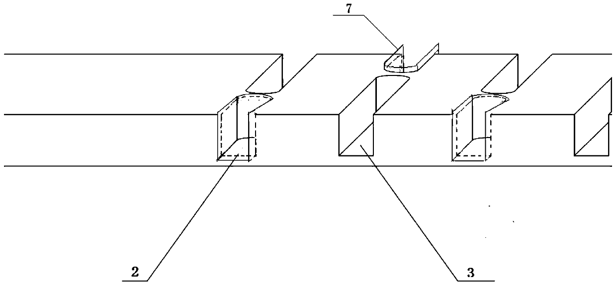
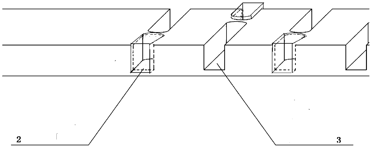
[0021] Such as figure 1 and figure 2 As shown, the positioning conductive row of the electrolyzer of the present invention includes a body 5, on the surface of the body 5 is provided with a plurality of rows of lap holes 1 for positioning the pole plate 4, and the lap holes 1 include mutually parallel pairs of mutually disconnected The insulating tap hole 2 and the conductive tap hole 3, the opposite and next to the insulating tap hole 2 is the conductive tap hole 3, the opposite and next to the conductive tap hole 3 is the insulating tap hole 2, the material of the body 5 is conductive material, and the insulating tap hole An insulating piece 7 made of insulating material is fixed inside the body 2, and the edge of the insulating piece 7 protrudes from the body 5.

[0022] Such as Figure 5 As shown, the insulating member 7 includes a bottom plate 71 attached to the insulating tap hole 2 , and a side plate 72 and an end plate 73 fixed on the bottom plate 71 . The bottom p...


PUM


Abstract

The invention relates to a positioning conducting bar of an electrolytic bath. The positioning conducting bar comprises a body; multiple rows of hanging holes for positioning polar plates are formed in the surface of the body and include insulated hanging holes and conducting hanging holes which are parallel with each other, are interactive pairwise and do not communicate with each other; the conducting hanging holes are formed opposite to and beside each insulated hanging hole; the insulated hanging holes are formed opposite to and beside each conducting hanging hole; the body is made of a conducting material; insulated pieces made of insulated materials are fixed in the insulated hanging holes; and the edges of the insulated pieces protrude out of the body. The positioning conducting barhas the advantages of reasonable structural design, stable electrolysis, high conductivity and the like.

Description

technical field [0001] The invention relates to a positioning component for an electrolytic cell, in particular to a positioning conductive bar for an electrolytic cell. Background technique [0002] At present, all kinds of domestic electrolysis processes need to use electrolytic cells, and all need to hang cathode and anode plates. The cathode and anode plates often have inaccurate positioning and non-parallel conditions between the plates, which may lead to uneven local current and uneven electrolysis, or lead to short-circuiting of the plates and short circuits in severe cases. In addition, during the electrolysis process, the conductive row between the tanks is exposed to the air, and the acid mist corrodes, and the dropped electrolyte makes the plates liquid-connected, causing a short circuit to burn the tank. [0003] Patent CN201220176036.1 A positioning insulating plate for the pole plate of an electrolytic cell. The positioning plate is an insulating matrix. Durin...

Claims


Application Information

Patent Timeline
Patent Type & Authority Patents(China)
IPC IPC(8): C25C7/00C25B9/00
CPCC25B9/00C25C7/00
Inventor 李环黄鹏飞黄建勇刘可人
Owner CHENZHOU CITY JINGUI SILVER IND CO LTD
Learn More