
Beamforming device and method for radio-over-optical communication based on arrayed waveguide grating

An arrayed waveguide grating, optical carrier wireless communication technology, applied in optical waveguide light guides, optical fiber radios, and equipment that generates/processes RF signals by optical methods, etc. Wide application, simple structure, high bandwidth effect

Active Publication Date: 2019-04-16
SOUTHWEST JIAOTONG UNIV
View PDF5 Cites 0 Cited by
  • Summary
  • Abstract
  • Description
  • Claims
  • Application Information

AI Technical Summary

Problems solved by technology

[0004] It should be pointed out that the above-mentioned photonic beamforming schemes all have the disadvantages of being too large and not easy to integrate, while the optical true delay device based on the arrayed waveguide grating (AWG) with multiple input and multiple output ports is small in size and easy to integrate. The advantages of integration have received extensive attention (Z.Cao, Q.Ma, A.B.Smolders, Y.Jiao, M.J.Wale, C.W.Oh, H.Wu, and A.M.J.Koonen, "Advanced integration techniques on broadband millimeter-wavebeam steering for 5G wireless networks and beyond,"IEEE Journal of Quantum Electronics,vol.52,no.1,article:0600620,Jan.2016)
In addition, the above scheme also has the problem that the delay difference between different channels is not easy to adjust; and in dynamic scenarios such as high-speed rail, the radiation direction of the radio frequency signal needs to be dynamically changed according to the movement of the train, so the lack of flexibility will greatly limit the photon beam. The scope of application of the shaping scheme

Method used


Image

  • Beamforming device and method for radio-over-optical communication based on arrayed waveguide grating
  • Beamforming device and method for radio-over-optical communication based on arrayed waveguide grating
  • Beamforming device and method for radio-over-optical communication based on arrayed waveguide grating

Examples


Embodiment Construction

[0027] The implementation of the present invention will be further described below in conjunction with the accompanying drawings.

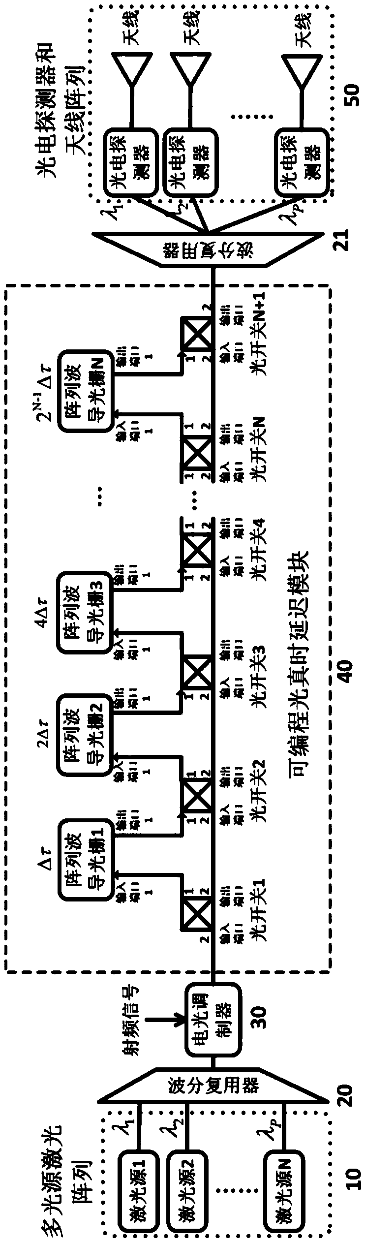
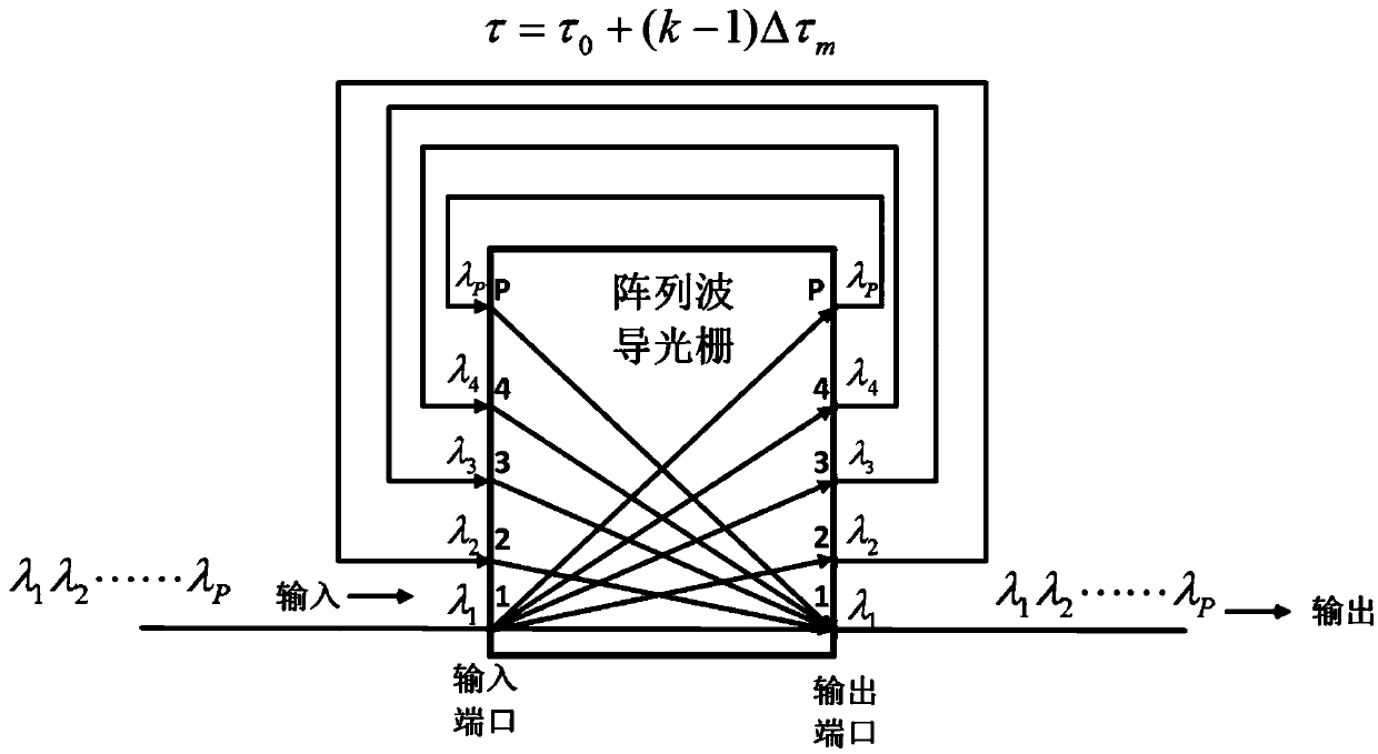
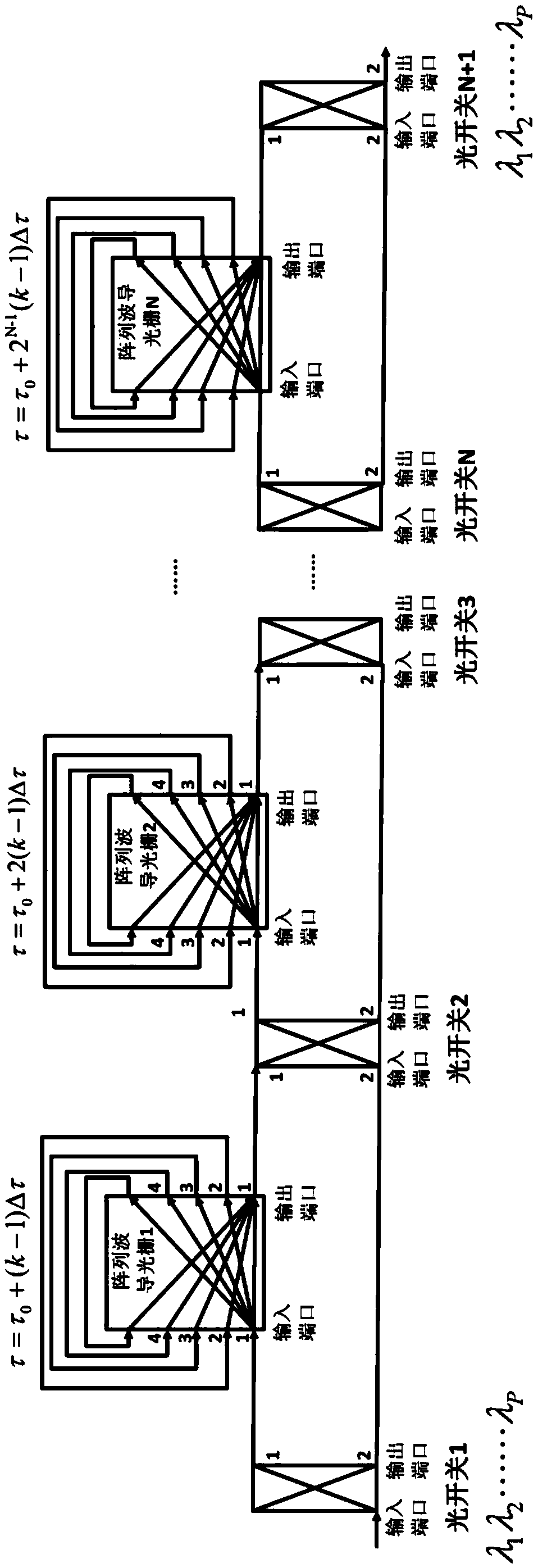
[0028] A beamforming system based on multiple-input multiple-output port arrayed waveguide grating (AWG) for optical wireless communication. The system consists of a multi-wavelength continuous laser source array 10, a wavelength division multiplexer 20, an electro-optic modulator 30, and an optical real time The delay module 40, the photodetector group and the antenna array 50 are composed. In this method, the radio frequency signal is modulated onto multiple wavelength carriers and processed in the optical domain by a broadband programmable optical delay module. The optical real-time delay module is composed of an optical switch and multiple cascaded AWGs that can provide basic delays between channels of different adjacent wavelengths. The basic delays of the AWGs of different levels are distributed in an equal ratio with a common ratio of 2. Fina...


PUM


Abstract

An arrayed waveguide grating-based optical wireless communication beamforming device and method thereof. The radio frequency signal is modulated onto multiple wavelength carriers, and processed by a programmable optical true delay module in the optical domain. This module is composed of an optical switch and multiple cascaded AWGs that can provide different basic delays between adjacent wavelength channels. Different levels The basic delay amount of the AWG is in a proportional distribution with a common ratio of 2. Optical carriers of different wavelengths enter different branches for photoelectric conversion to recover radio frequency signals with different delays (phases), realizing the far-field beam directional radiation mode. The invention has the characteristics of broadband, adjustable, flexible, small volume and easy integration, etc., and has very important applications in dynamic scenes such as next-generation mobile communication and high-speed railway.

Description

Technical field [0001] The invention relates to an optical carrier wireless communication system, in particular to a beamforming system and a method based on the true time delay of photons. Background technique [0002] The beamforming technology realizes the spatial focusing of the radio frequency signal in a specific direction by controlling the amplitude and phase of each element of the array antenna (beam directional radiation mode), which can effectively reduce signal transmission loss, increase coverage, and reduce energy Interference to the surrounding signal receiving end caused by diffusion. Therefore, beamforming technology has very important applications in radio frequency and microwave fields such as radar and wireless communications. However, the current beamforming technology based on electronic methods is limited by the "electronic bottleneck" and instantaneous bandwidth, and cannot meet the development needs of radar technology and next-generation wireless commun...

Claims


Application Information

Patent Timeline
Patent Type & Authority Patents(China)
IPC IPC(8): H04J14/02H04B7/06G02B6/12
CPCH04B7/0617H04J14/0205G02B6/12009H04B2210/006H04B10/2575H04B10/503H04B10/506
Inventor 邹喜华李沛轩潘炜
Owner SOUTHWEST JIAOTONG UNIV
Learn More