Inverted cold-bent U-shaped steel composite beam bridge connected through lacing bars and construction method

A U-shaped steel, inverted technology, used in bridges, bridge parts, bridge construction and other directions, can solve the problems of low overall stiffness and torsion resistance of bridges, poor lateral stability of bridge structures, endangering traffic and pedestrian safety, etc. Small hoisting capacity, reduced anti-corrosion workload and less fatigue damage

Pending Publication Date: 2018-04-13
CHANGAN UNIV
View PDF9 Cites 3 Cited by
  • Summary
  • Abstract
  • Description
  • Claims
  • Application Information

AI Technical Summary

Problems solved by technology

In the traditional cold-formed U-shaped steel composite girder bridge, there is no certain horizontal connection between the main girders. During the construction and use of the bridge, the transverse direction of the cold-formed U-shaped steel composite girder bridge can only be connected by the bridge deck. As a result, the lateral stability of the bridge structure is poor, the overall stiffness and torsion resistance of the bridge are low, and the span of the bridge is limited
If this type of bridge is used within a relatively large span range (40-80m), it may be that the main girder is under a single piece of force due to insufficient transverse overall rigidity, endangering the safety of traffic and pedestrians

Method used


Image

  • Inverted cold-bent U-shaped steel composite beam bridge connected through lacing bars and construction method
  • Inverted cold-bent U-shaped steel composite beam bridge connected through lacing bars and construction method
  • Inverted cold-bent U-shaped steel composite beam bridge connected through lacing bars and construction method

Examples


Embodiment Construction

[0040] The technical scheme of the present invention will be described in further detail below with reference to the accompanying drawings.

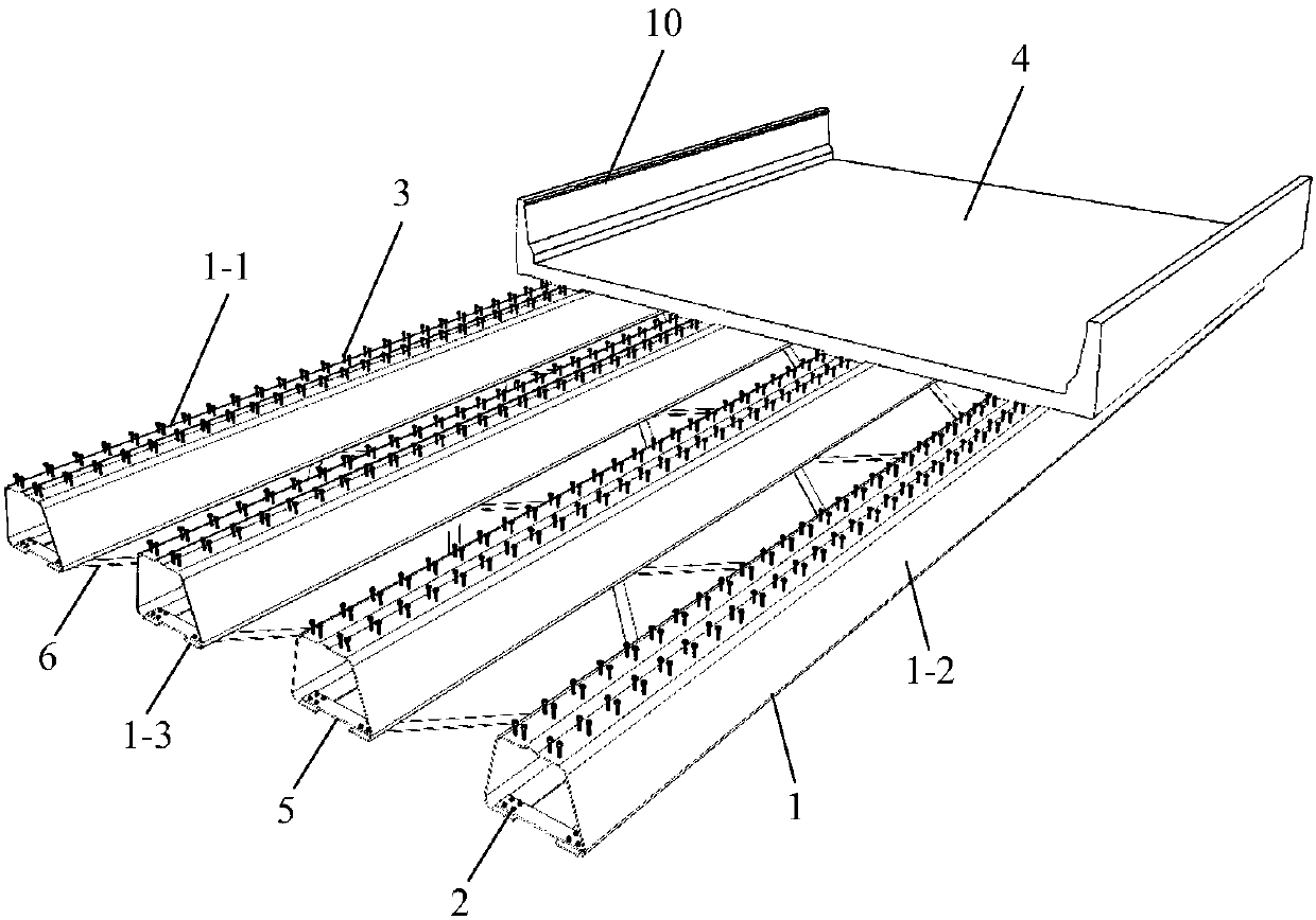
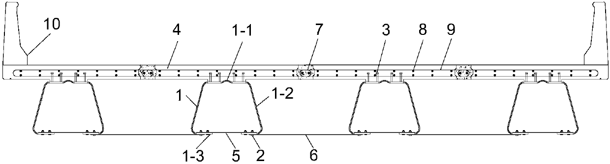
[0041] Such as figure 1 , figure 2 , image 3 , Figure 4 , Figure 5 , Figure 6 , Figure 7 and Figure 8 As shown, the present invention includes: some cold-formed U-shaped steel girders 1 and prefabricated concrete bridge decks 4 arranged in parallel, some shear nails 3 are welded on the top surface of some cold-formed U-shaped steel beams 1, and some shear nails 3 A precast concrete bridge deck 4 is arranged on it, that is, the precast concrete bridge deck 4 is set on the cold-formed U-shaped steel girder 1 through shear nails 3 .

[0042] Each cold-formed U-shaped steel beam 1 includes an upper flange plate 1-1 and a lower flange plate 1-3, and a web 1-2 is arranged between the upper flange plate 1-1 and the lower flange plate 1-3 , the upper flange plate 1-1, the lower flange plate 1-3 and the web 1-2 form a trapezoidal s...


PUM

PropertyMeasurementUnit
Widthaaaaaaaaaa
Vertical spacingaaaaaaaaaa

Abstract

Provided are an inverted cold-bent U-shaped steel composite beam bridge connected through lacing bars and a construction method. The inverted cold-bent U-shaped steel composite beam bridge connected through the lacing bars comprises a plurality of cold-bent U-shaped steel beams which are arranged in parallel, wherein the cold-bent U-shaped steel beams are provided with prefabricated concrete bridge panels; each cold-bent U-shaped steel beam comprises an upper flange plate and a lower flange plate, webs are arranged between the upper flange plates and the lower flange plates, and the upper flange plates, the lower flange plates and the webs form structures with the cross sections as trapezoids; each lower flange plate comprises two lower flange plate bodies which are arranged at an interval, and the two ends of each two lower flange plate bodies which are arranged at the interval are connected through the corresponding beam bottom lacing bars. According to the inverted cold-bent U-shaped steel composite beam bridge connected through the lacing bars, the force transmission efficiency is high, the flexural rigidity is greatly improved, steel material consumption is saved, and good economic benefit can be obtained; the U-shaped steel beams can be prefabricated and spliced in an industrial mode, so that the construction requirements are fast met; meanwhile, according to the bridge,under the condition that safety, the practicability and economy are achieved, the shape is novel and compact, and the bridge can well harmonize with the environment.

Description

technical field [0001] The invention relates to the technical field of bridge construction, in particular to an inverted cold-formed U-shaped steel composite girder bridge connected by strips and a construction method. Background technique [0002] Due to its economic and technical advantages, cold-formed U-shaped steel composite girder bridges are widely used in small and medium-span bridge projects, especially for bridges with spans ranging from 5 to 18 m. The main girders of the traditional cold-formed U-shaped steel composite girder bridge do not have a certain horizontal connection. During the construction and use of the bridge, the transverse direction of the cold-formed U-shaped steel composite girder bridge can only be connected by the bridge deck. As a result, the lateral stability of the bridge structure is poor, the overall stiffness and torsion resistance of the bridge are low, and the span of the bridge is limited to a certain extent. If this type of bridge is ...

Claims


Application Information

Patent Timeline
IPC IPC(8): E01D1/00E01D21/00E01D19/00
CPCE01D1/00E01D19/00E01D21/00
Inventor 刘永健李江江王文帅张轩瑜王建平刘城
Owner CHANGAN UNIV
Why Eureka
Try Eureka