Installation construction technology of open mounted lightning receiving strip supported by casing pipe
A construction technique and lightning-termination belt technology, which is applied in the installation of cables, installation of lighting conductors, and processing of building materials, can solve problems affecting lightning protection grounding systems, shortening service life, and damaging galvanized layers, etc., to improve construction Work efficiency, prolong service life, save the effect of welding construction
- Summary
- Abstract
- Description
- Claims
- Application Information
AI Technical Summary
Problems solved by technology
Method used
Image
Examples
Embodiment 1
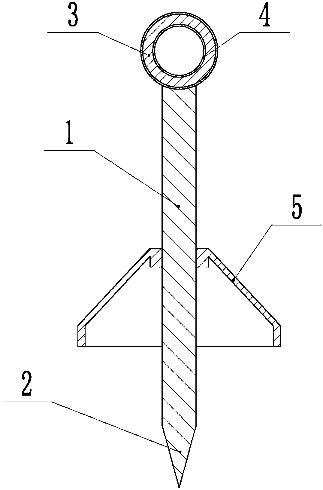
[0024] Embodiment 1 Basic Reference figure 1 As shown in , the installation process of surface-mounted lightning-termination belt supported by casing includes the following steps:
[0025] A. Manufacture of the casing bracket: Cut the material according to the schematic diagram of the casing bracket, intercept the galvanized round steel with a length of 230mm: the height of the exposed parapet is 150mm, the depth of the buried parapet is 80mm, the length of the galvanized steel pipe is 50mm, and the burrs are polished After that, after the preliminary welding process is completed, it will be sent to the factory for hot-dip galvanizing treatment;
[0026] B. Sleeve support positioning: Set the end point sleeve support on the wall at a distance of 300mm from the corner at both ends of the horizontal straight line section of the wall, and install the sleeves in the middle section between each two end points. The distance between brackets and casing brackets shall be 70mm; after ...
Embodiment 2
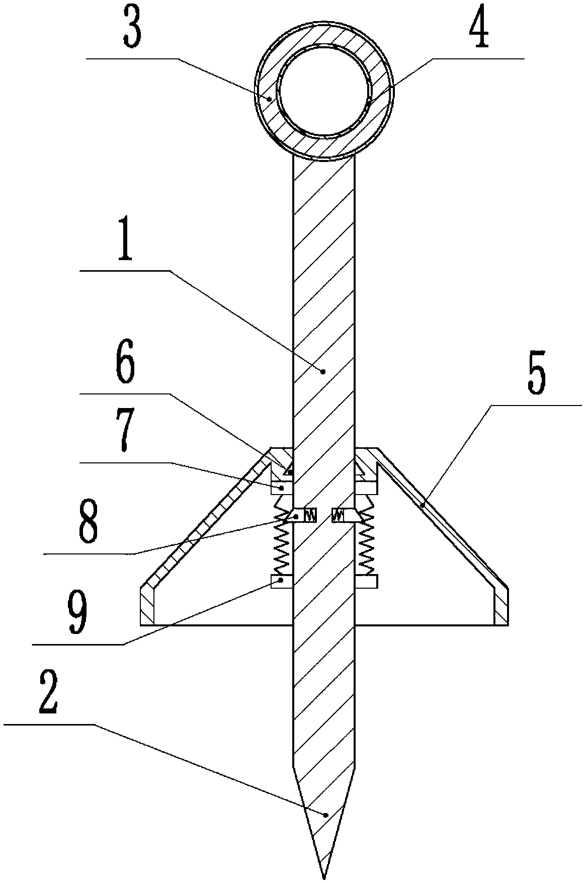
[0029] Example 2 reference figure 2 As shown, compared with Embodiment 1, the difference is that the decorative cover is slidably connected to the support column, and the support column is located below the decorative cover and is slidably connected with the first wedge, and the top of the decorative cover is against the top of the first wedge. A fixed block is welded on the support column below the first wedge, a first spring is welded between the first wedge and the fixed block, an opening is opened on the support column between the first wedge and the fixed block, and the sliding connection extension in the opening is The second wedge comes out of the opening, the second wedge is against the first wedge, the second spring is welded between the second wedge and the opening wall, and the top of the decorative cover is provided with a limit for the insertion of the second wedge hole.
[0030] After fixing the support column on the wall, slide the decorative cover downwards, ...
Embodiment 3
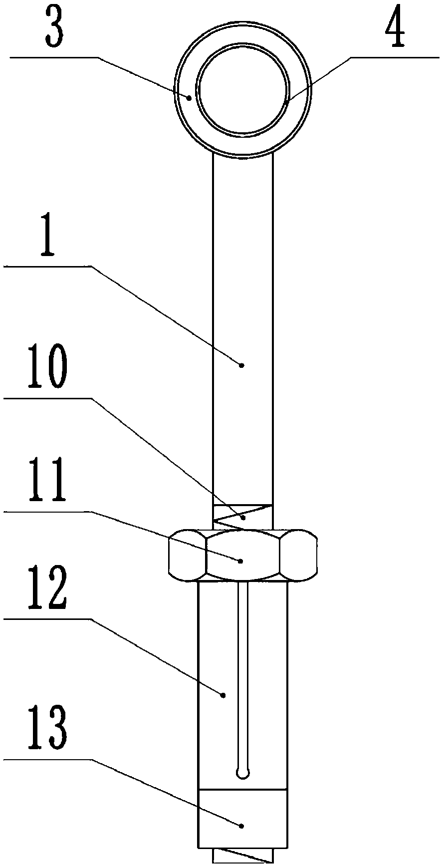
[0031] Example three reference image 3 As shown, compared with Embodiment 1, the difference is that an expansion bolt is installed at the bottom of the support column, and the expansion bolt includes a screw rod, a nut, an expansion sleeve and a fixed sleeve, the bottom of the support column is a screw rod, and the nut is threaded on the screw rod. The bottom is welded with a fixed sleeve, and an expansion sleeve is set between the fixed sleeve and the nut.
[0032] Insert the expansion bolt at the bottom of the support column into the installation hole, screw the nut of the expansion bolt, the expansion sleeve of the expansion bolt will expand and perform interference fit with the wall of the installation hole, so that the support column is fixed.
[0033] Embodiment 4-embodiment 7, compared with embodiment one, its difference is, as shown in the table below:
[0034]
[0035]
PUM
 Abstract
Description
Claims
Application Information
 - R&D
- Intellectual Property
- Life Sciences
- Materials
- Tech Scout
- Unparalleled Data Quality
- Higher Quality Content
- 60% Fewer Hallucinations
Browse by: Latest US Patents, China's latest patents, Technical Efficacy Thesaurus, Application Domain, Technology Topic, Popular Technical Reports.
© 2025 PatSnap. All rights reserved.Legal|Privacy policy|Modern Slavery Act Transparency Statement|Sitemap|About US| Contact US: help@patsnap.com


