
Furnace chamber clearing device for vacuum consumable electro-arc furnace

A vacuum consumable arc and cleaning device technology, applied in the direction of descaling devices, furnaces, furnace components, etc., can solve the problems of reduced cleaning efficiency, falling of metal or non-metallic volatiles, poor adaptability of furnace room cleaning devices, etc. Achieve the effect of improving cleaning effect, improving adaptability and practicality

Inactive Publication Date: 2018-04-06
BAOJI JINSHENGYUAN TITANIUM IND
View PDF5 Cites 0 Cited by
  • Summary
  • Abstract
  • Description
  • Claims
  • Application Information

AI Technical Summary

Problems solved by technology

[0004] In order to achieve the above object, the present invention provides a furnace chamber cleaning device for vacuum consumable electric arc furnace, which cleans thoroughly and is not easy to produce dead corners, and solves the problem of poor adaptability of the furnace chamber cleaning device in the prior art and the adhesion of the furnace chamber wall during the cleaning process. The metal or non-metallic volatiles fall off and need to be cleaned again, which reduces the cleaning efficiency

Method used


Image

  • Furnace chamber clearing device for vacuum consumable electro-arc furnace
  • Furnace chamber clearing device for vacuum consumable electro-arc furnace

Examples


Embodiment Construction

[0013] The following will clearly and completely describe the technical solutions in the embodiments of the present invention with reference to the accompanying drawings in the embodiments of the present invention. Obviously, the described embodiments are only some, not all, embodiments of the present invention. Based on the embodiments of the present invention, all other embodiments obtained by persons of ordinary skill in the art without making creative efforts belong to the protection scope of the present invention.

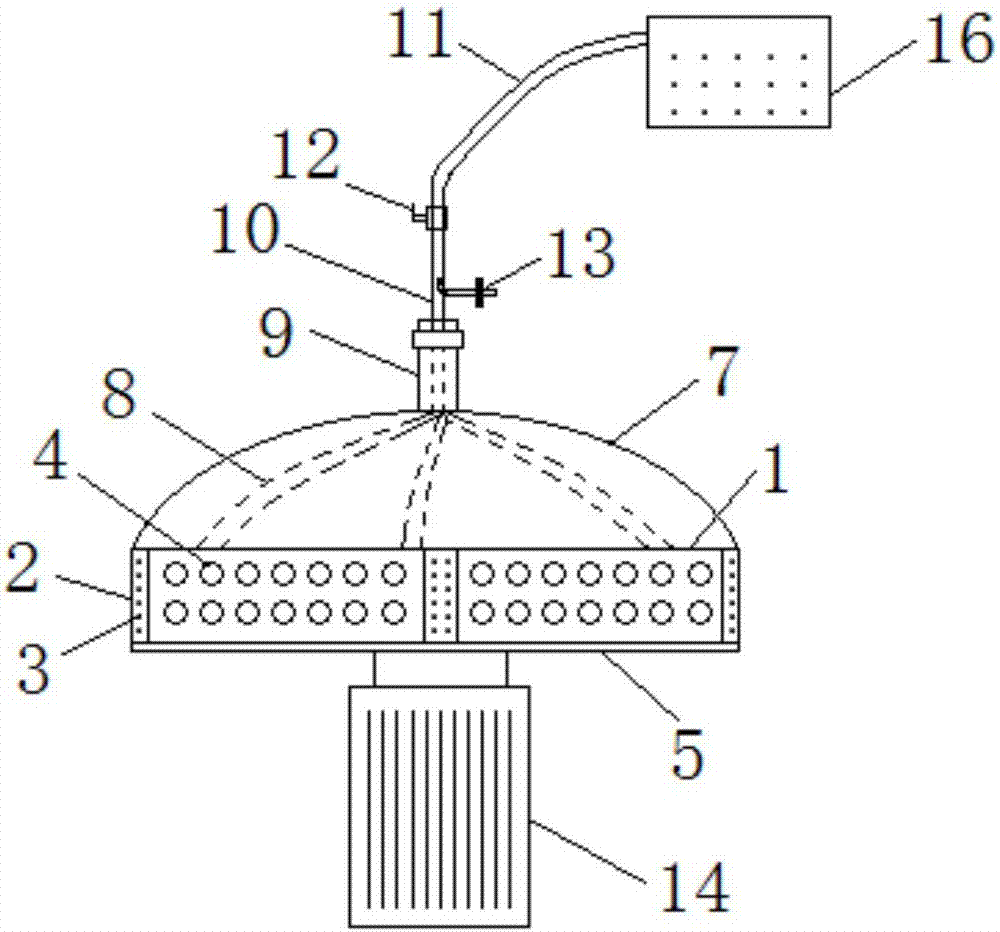
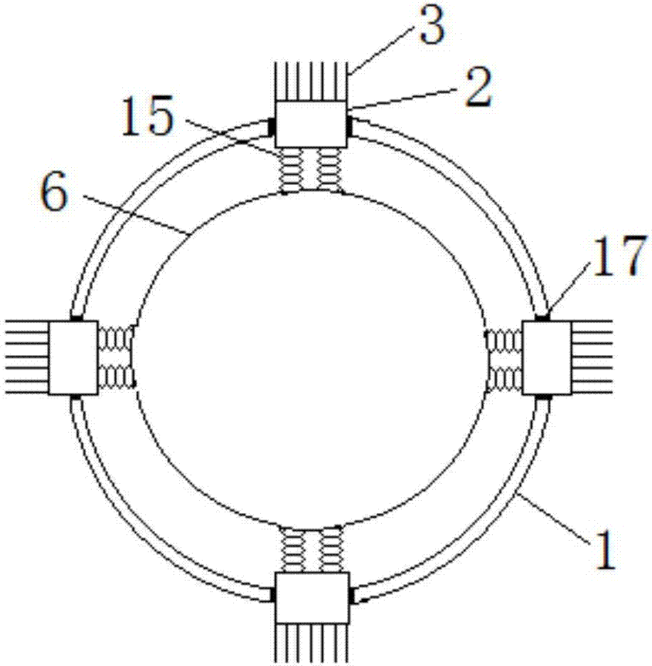
[0014] The structure of the embodiment of the present invention, such as Figure 1-2 As shown, the bottom of the cleaning turntable 1 is detachably connected with a bottom cover 5, and the center position of the cleaning turntable 1 is connected with the rotating shaft of the motor 14. The inside of the cleaning turntable 1 is provided with an inner ring 6, which is coaxial with the cleaning turntable 1. The side wall of the turntable 1 is evenly provided with...


PUM

PropertyMeasurementUnit
Apertureaaaaaaaaaa

Abstract

The invention discloses a furnace chamber clearing device for a vacuum consumable electro-arc furnace. The center position of a clearing rotary disc is connected with a rotary shaft of a motor, and aninner ring is arranged in the clearing rotary disc. A plurality of sliding grooves are evenly formed in the side wall of the clearing rotary disc, and each sliding groove is internally provided witha clearing head. Brush bristles are arranged on the outer side faces of the clearing heads, and the inner side faces of the clearing heads are connected with an inner ring through springs. A pluralityof dust sucking holes are evenly formed in the side wall of the clearing rotary disc and between every two adjacent sliding grooves, and an arc-shaped dust collecting hood is arranged at the top of the clearing rotary disc. The top of the dust collecting hood is provided with a connecting head which is internally provided with a first dust sucking pipe, one end of the first dust sucking pipe communicates with the dust collecting hood, and the other end of the first dust sucking pipe stretches out of the connecting head and then is connected with a dust collector through a second dust suckingpipe. A valve is arranged on the position, close to the second dust sucking pipe, of the first dust sucking pipe, and a compressed air inlet pipe is arranged on the position, between the valve and theconnecting head, of the first dust sucking pipe. According to the furnace chamber clearing device, the problems that an existing furnace chamber clearing device is poor in adaptability and low in sweeping efficiency are solved.

Description

technical field [0001] The invention belongs to the technical field of metal smelting equipment, and relates to a furnace chamber cleaning device for a vacuum consumable electric arc furnace. Background technique [0002] During the smelting process of vacuum consumable electric arc furnace, due to the volatilization of alloy elements, a layer of metal or non-metallic volatiles adheres to the inner wall of the furnace. In order to avoid affecting the crystal quality in the next smelting, it needs to be cleaned in time; the traditional cleaning method is mostly Manual operation, cleaning with a rag, this method is a point-type operation, the cleaning is not thorough, and it is easy to produce dead ends, which will bring pollution sources to the next process and reduce the melting effect. [0003] Some existing furnace chamber cleaning devices use automatic mechanisms instead of manual cleaning, but there are still the following problems: the relative position of the brush hea...

Claims


Application Information

Patent Timeline
IPC IPC(8): F27B3/08F27B3/10F27D25/00
CPCF27B3/085F27B3/10F27D25/00
Inventor 高世鹏白小英高皓
Owner BAOJI JINSHENGYUAN TITANIUM IND
Learn More