
Gear and rack transmission mechanism suitable for circular motion

A technology of rack and pinion, transmission mechanism, applied in the direction of transmission device, friction transmission device, belt/chain/gear, etc., can solve the problems of not being able to do circular motion and circular transmission, etc. The effect of adaptive, good manufacturability

Pending Publication Date: 2018-04-06
CHINA RAILWAY BAOJI BRIDGE GRP
View PDF0 Cites 2 Cited by
  • Summary
  • Abstract
  • Description
  • Claims
  • Application Information

AI Technical Summary

Problems solved by technology

[0003] Aiming at the problem that the above-mentioned existing gear-rack transmission with non-sector teeth and conical teeth can only do linear motion and cannot perform circular transmission, the present invention proposes a rack and pinion transmission mechanism suitable for circular motion. In the way of straight instead of curved, the standard racks are used to form sector teeth, and the spherical inner ring and spherical outer ring are designed inside the drive external gear to form a spherical rotating device to mesh the teeth, thereby realizing circular motion, and solving the problem of non-sector teeth. , The gear-rack transmission of bevel gears cannot do circular motion, and the standard rack-gear circular drive has been realized.

Method used


Image

  • Gear and rack transmission mechanism suitable for circular motion
  • Gear and rack transmission mechanism suitable for circular motion
  • Gear and rack transmission mechanism suitable for circular motion

Examples


Embodiment Construction

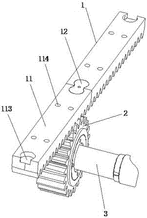
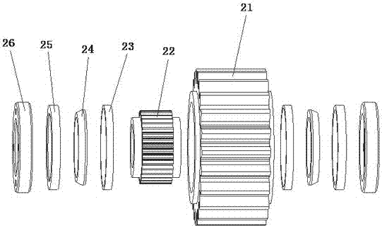
[0022] Such as Figures 1 to 7 As shown, the present invention is applicable to a circular motion rack and pinion transmission mechanism, including a circumferential rack arrangement assembly 1 and a drive gear assembly 2 .

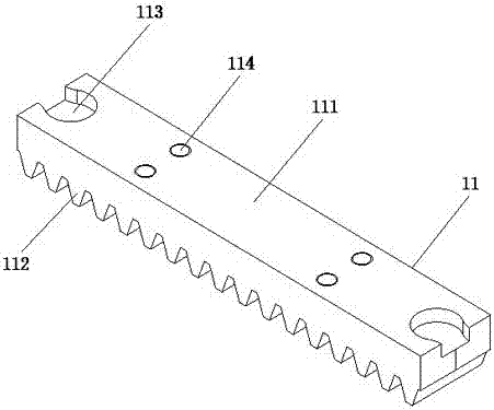
[0023] The circumferential rack arrangement assembly 1 is fixed on the arc-shaped base frame, which includes a rack 11 and a rack positioning connection 12; two adjacent racks 11 are connected by a rack positioning connection 12, realizing The reliable positioning of the rack 11, the continuous force of the rack 11; wherein, each segment of the rack 11 is linear and is arranged in a straight line instead of a curve, and each segment of the rack 11 is composed of a rectangular rack block 111 and Composed of a plurality of teeth 112 evenly arranged on the front of the rack block 11, the two ends of the back of the rack block 111 are symmetrically provided with a half drum-shaped keyway 113, and there are two sets of assembly parts between the two ends of th...


PUM


Abstract

The invention relates to a gear and rack transmission mechanism suitable for circular motion. The gear and rack transmission mechanism comprises a circumferential rack arrangement assembly and a driving gear assembly; the circumferential rack arrangement assembly is fixed to an arc-shaped basic support, and the driving gear assembly is connected to a driving shaft in a sleeving manner and is matched and meshed with the circumferential rack arrangement assembly; the circumferential rack arrangement assembly comprises a rack; the driving gear assembly comprises a driving outer gear and a drivinginner gear; the rack is linear and achieves circumferential arrangement in a manner of replacing a curve with a straight line; the overall driving gear assembly can rotate around the driving shaft; and tooth structures of the driving outer gear and the driving inner gear are crowned teeth. According to the gear and rack transmission mechanism, the standard rack forms fan-shaped teeth, the drivingouter gear is meshed with the teeth, and therefore circular motion is achieved, the problem that gear-rack transmission of non-fan-shaped teeth and taper gears cannot do circular motion is solved, and the standard rack-gear circumferential driving is achieved.

Description

technical field [0001] The invention relates to the technical field of mechanical transmission, in particular to a rack and pinion transmission mechanism suitable for circular motion. Background technique [0002] In the existing peripheral drive gear-rack system, the rack is usually made into sector teeth and the gear is made into bevel gears, but this structure is not suitable for transmission systems with large circumference radius. The gear-rack transmission system with non-segment teeth and bevel teeth can only transmit linear motion, but cannot transmit circular motion. Contents of the invention [0003] Aiming at the problem that the above-mentioned existing gear-rack transmission with non-sector teeth and conical teeth can only do linear motion and cannot perform circular transmission, the present invention proposes a rack and pinion transmission mechanism suitable for circular motion. In the way of straight instead of curved, the standard racks are used to form s...

Claims


Application Information

Patent Timeline
Patent Type & Authority Applications(China)
IPC IPC(8): F16H19/04
CPCF16H19/04
Inventor 余锋都武牛均宽
Owner CHINA RAILWAY BAOJI BRIDGE GRP
Learn More