Main engine room cover locking structure of unmanned drug spraying machine

A technology for the main cabin and spraying machine, which is applied to aircraft parts, building structures, building fastening devices, etc. It can solve the problems of increasing the difficulty of operation, loosening of the main cabin cover, and difficulty in processing and manufacturing, so as to achieve easy implementation, Easy to process and assemble, easy to process and produce

Inactive Publication Date: 2018-04-06
刘福珍
View PDF5 Cites 0 Cited by
  • Summary
  • Abstract
  • Description
  • Claims
  • Application Information

AI Technical Summary

Problems solved by technology

Due to the small parts, there are disadvantages such as difficult processing, difficult assembly, high production cost, etc.
In addition, two-point or three-point locking is adopted. On the one hand, multiple locking points must be operated at the same time, which increases the difficulty of operation; on the other hand, the reliability after locking is still insufficient, which may cause the engine compartment The cover is loose or making abnormal noises

Method used


Image

  • Main engine room cover locking structure of unmanned drug spraying machine
  • Main engine room cover locking structure of unmanned drug spraying machine

Examples


Embodiment Construction

[0016] Below in conjunction with accompanying drawing and embodiment the present invention will be further described:

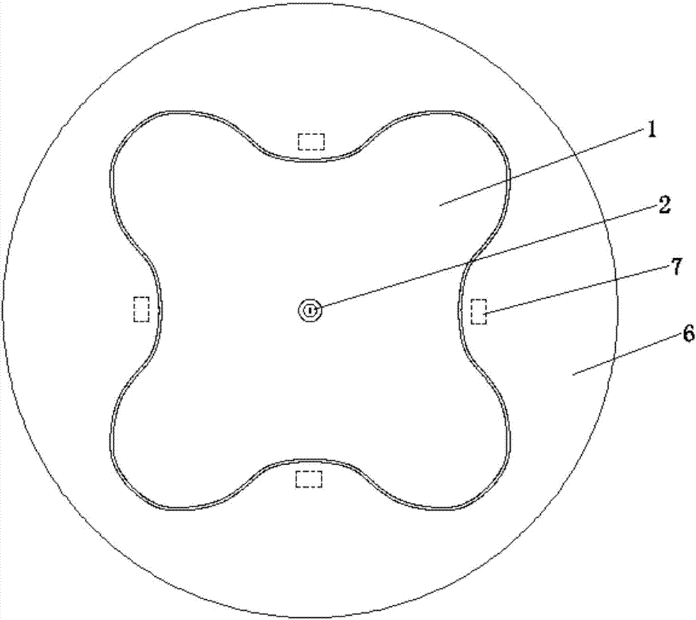
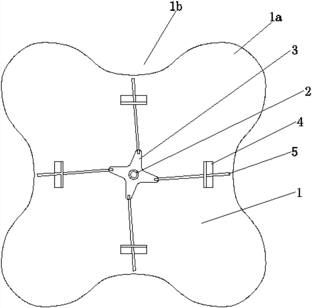
[0017] like figure 1 , figure 2 Shown, the present invention is made up of main engine compartment 6 and main engine compartment cover 1 two major parts. Wherein, the main engine compartment cover 1 is a spherical structure with a high center and a low edge. The outer edge of the main engine compartment cover 1 is integrally formed with four flanges 1a uniformly distributed on the circumference. The flanges 1a are arc-shaped, and there is a smooth transition between two adjacent flanges 1a through depressions 1b. The top of the main cabin 6 is provided with an opening, the shape and size of which are adapted to the main cabin cover 1, and the main cabin cover 1 is fastened to the opening at the top of the main cabin 6 to seal the opening. The inner space of the main engine compartment 6 is divided into upper and lower parts independent of each other by a ...


PUM


Abstract

The invention discloses a main engine room cover locking structure of an unmanned drug spraying machine. A main engine room cover is mounted at an opening of the top of a main engine room in a buckledmode, the shape and the size of the main engine room cover adapt to the opening of the top of the main engine room, a lockset is mounted at the center of the main engine room cover in an embedded mode, a servo block is fixed to the lower end of a lock core, and the four suspending ends of the servo block correspond to four guiding blocks correspondingly. Each guiding block is equipped with a lockrod, the outer ends of the lock rods penetrate through guiding holes correspondingly formed in the guiding blocks, and can extend into an elastic lock clamp arranged on the inner wall of the top endof the main engine room. The interior space of the main engine room is divided into an upper part and a lower part which are independent from each other by a separation plate, the upper part is an equipment room, and the lower part is a drug liquid room. The main engine room cover locking structure of the unmanned drug spraying machine is reasonable in design, simple in structure, easy to implement and easy to machine, produce and assemble, the locking reliability of the main engine room cover on the main engine room can be ensured while the production cost is reduced effectively, meanwhile operation is convenient, and labor is saved. According to the main engine room cover locking structure, a space for storing drug liquid can be reserved in the main engine room, and the height dimensionof the unmanned drug spraying machine is reduced greatly.

Description

technical field [0001] The invention belongs to the technical field of agricultural machinery, and in particular relates to a locking structure for a main cabin cover of an unmanned spraying machine. Background technique [0002] At present, the UAV that sprays pesticides automatically generally includes a main engine cabin, a cantilever and a power cabin, and the opening on the top of the main engine cabin is sealed by the main engine cabin cover. The existing main engine compartment cover is usually connected to the main engine compartment in two ways, one is a flip-lock type, and the other is a snap-fit ​​lock type. Due to the poor reliability of the flip lock type, the snap lock type main engine compartment cover has gradually become the mainstream. [0003] The existing buckle-locking main engine compartment cover is generally locked by turning the lock bar, and the lock bar is reset by the elastic force of the spring. Due to the small parts, there are disadvantages s...

Claims


Application Information

Patent Timeline
Patent Type & Authority Applications(China)
IPC IPC(8): E05C9/06E05C9/18E05C9/22B64D1/18
CPCE05C9/063B64D1/18E05C9/006E05C9/1825E05C9/22
Inventor 刘博文刘福珍
Owner 刘福珍
Why Eureka
Try Eureka