
Construction method for thermal bridge partition type enclosure system

A construction method and partition-type technology, applied in the field of outdoor prefabricated integrated buildings, can solve the problems of uneven heat conduction of the wall insulation layer, condensation on the inner wall of the house, pollution of the construction environment, etc., so as to solve the thermal bridge effect, low cost, The effect of prolonging the service life

Active Publication Date: 2018-04-06
江苏浦相新材料科技有限公司
View PDF5 Cites 2 Cited by
  • Summary
  • Abstract
  • Description
  • Claims
  • Application Information

AI Technical Summary

Problems solved by technology

[0006] At present, the enclosure system is the bottleneck of prefabricated integrated buildings, especially for outdoor prefabricated integrated buildings, the temperature difference between indoor and outdoor is large in late autumn and early winter, frequent contact of hot and cold air, uneven heat conduction of wall insulation layer, resulting in thermal bridge effect, Condensation, mildew and even dripping on the inner wall of the house are caused. At present, in order to solve this thermal bridge effect, after cleaning the wall of the moldy part, the wall faces outward along the junction of the floor and the wall, and the junction of the inner wall and the outer wall. Widening can achieve the purpose of improving wall insulation and moisturizing, reducing heat transfer, and effectively solving the thermal bridge effect. However, the disadvantage of this method is that the cost is too high. At the same time, the current construction method of the enclosure system uses wet operation, which is difficult for transportation and The construction brings a lot of inconvenience, and at the same time pollutes the construction environment, which is time-consuming and laborious

Method used


Image

  • Construction method for thermal bridge partition type enclosure system
  • Construction method for thermal bridge partition type enclosure system
  • Construction method for thermal bridge partition type enclosure system

Examples


Embodiment Construction

[0052] In order to deepen the understanding of the present invention, the present invention will be further described below in conjunction with the embodiments and accompanying drawings. The embodiments are only used to explain the present invention and do not constitute a limitation to the protection scope of the present invention.

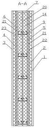
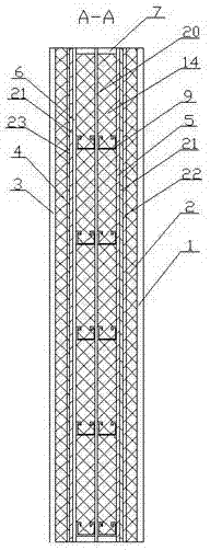
[0053] In this embodiment, a construction method of a thermal bridge partition enclosure system, such as figure 1 As shown, the thermal bridge partition containment system includes

[0054] A frame mechanism, the frame mechanism is formed by connecting two layers of skeleton groups side by side, and the joint between the two layers of skeleton groups is provided with a thermal insulation cushion 20, such as Figure 4 As shown, the skeleton group includes an outer frame of a frame-like structure composed of four U-shaped pieces 7, a connecting piece 8 placed horizontally inside the outer frame, and a plurality of vertically evenly arranged support...


PUM

PropertyMeasurementUnit
Thermal conductivityaaaaaaaaaa

Abstract

The invention relates to a construction method for a thermal bridge partition type enclosure system. The construction method comprises the specific steps: (1) building an enclosure system, namely a, manufacturing a framework mechanism; b, building a structure reinforcing mechanism; c, building a moisture-proof partition mechanism; and d, building decorative inner wall boards and insulation decorative boards; and (2) mounting the enclosure system on the wall, namely connecting the enclosure system built in the step (1) with a building wall by fixing screws, thus tightly connecting the decorative inner wall boards of the enclosure system with the building wall, and while fixing the screws, guaranteeing that the distance between the two adjacent screws is 500mm, and fixing screws at two endsof the building wall being less than or equal to 500mm by a spacing of 50mm. The construction method disclosed by the invention has the advantages of capabilities of reducing the cost, effectively solving the thermal bridge effect and integrating multiple functions of heat insulation, sound insulation, waterproofing and decoration into a whole, and simplicity and convenience in operation.

Description

Technical field: [0001] The invention relates to the field of outdoor prefabricated integrated buildings, in particular to a construction method of a thermal bridge partition enclosure system. Background technique: [0002] Prefabricated integrated buildings are the focus of national strategic development. By 2020, the proportion of prefabricated buildings in the country will account for more than 15% of new buildings. Special emphasis is placed on promoting full decoration and menu-style decoration of buildings. The policy support for the development of prefabricated buildings is unprecedented. The modern construction industry is entering the fast lane. At present, prefabricated buildings mainly include concrete buildings, wood structure buildings, and steel structure buildings. [0003] Prefabricated concrete buildings generally use prefabricated wall panels and components, which are heavy, generally more than 1,000 kilograms per square meter, and have high requirements f...

Claims


Application Information

Patent Timeline
IPC IPC(8): E04C2/00E04B1/76
CPCE04B1/7608E04C2/00
Inventor 施春雄许坤明
Owner 江苏浦相新材料科技有限公司
Learn More