Plank punching device

A punching device and wood board technology, which is applied to fixed drilling machines and other directions, can solve the problems of low work efficiency, inability to ensure the accuracy of punching holes, and simultaneous punching of multiple round holes on wood boards, and achieve a wide range of applications.

Inactive Publication Date: 2018-04-06
湖州南浔朝木阳木制品厂
View PDF0 Cites 4 Cited by
  • Summary
  • Abstract
  • Description
  • Claims
  • Application Information

AI Technical Summary

Problems solved by technology

[0002] At present, due to its convenient processing and certain strength, wood is widely used in our production and life, and is closely related to each of us. Wood is used by us to build houses, decorate indoor environments, and make indoor furniture. In the process, especially the processing of wood boards, it is necessary to punch the wood boards according to the needs. The traditional wood board punching device generally uses the worker to hold the punching head to punch the wood boards. The labor intensity of the workers is relatively high, and the work efficiency is relatively high. Low, especially when it is necessary to punch multiple round holes at equal intervals on a board, due to the randomness of the workers' operation, it is difficult to accurately punch holes on the board, which affects the quality of the board's punching. The whole set of punching mechanism is used to punch the wooden board, but in the process of punching the wooden board, it is difficult to punch multiple round holes synchronously according to the needs, and the accuracy of the punching cannot be guaranteed, which reduces the efficiency and quality of the punching. Can not meet the needs of production use

Method used


Image

  • Plank punching device

Examples


Embodiment Construction

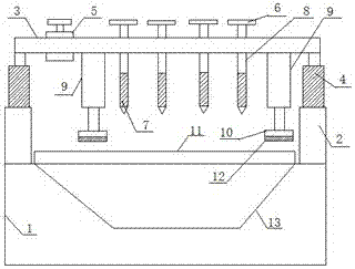
[0013] The present invention will be further described below in conjunction with the accompanying drawings and specific embodiments.

[0014] Such as figure 1 A kind of plank punching device shown comprises workbench 1, support frame 2, cross bar 3, hydraulic cylinder 4, motor 5, transmission wheel 6, drill rod 7, and described support frame 2 is arranged on the two sides of workbench 1 On the side, two support frames 2 on both sides of the workbench 1 are respectively provided with a hydraulic cylinder 4, and the piston rods of the two hydraulic cylinders 4 are connected by a cross bar 3, and the cross bar 3 is provided with a motor 5 and a plurality of transmissions. Wheel 6, motor 5 is connected with transmission wheel 6 through belt, and the center of described transmission wheel 6 is provided with the transmission rod 8 that is connected with drilling rod 7, and the end of transmission rod 8 is provided with the internal thread that is opposite to transmission wheel 6, T...


PUM


Abstract

The invention discloses a plank punching device, which comprises a workbench, a support frame, a cross bar, a hydraulic cylinder, a motor, a transmission wheel, and a drill rod. The support frame is arranged on both sides of the workbench. A hydraulic cylinder is respectively arranged on each supporting frame, and the piston rods of the two hydraulic cylinders are connected by a cross bar. The cross bar is provided with a motor and a plurality of transmission wheels, and the motor is connected with the transmission wheel through a belt. The center of the transmission wheel There is a drive rod connected with the drill rod, the end of the drive rod is provided with an internal thread opposite to the drive wheel, the upper end of the drill rod is provided with an external thread and connected with the end of the drive rod, and the cross bar is provided with There is a compacting cylinder for compacting the plank, the piston end of the compacting cylinder is connected with a compacting block, and the workbench is provided with a punching groove arranged horizontally. The device can punch a plurality of holes at the same time, has high efficiency, and the punching position is accurate.

Description

technical field [0001] The invention relates to a wood board punching device. Background technique [0002] At present, due to its convenient processing and certain strength, wood is widely used in our production and life, and is closely related to each of us. Wood is used by us to build houses, decorate indoor environments, and make indoor furniture. In the process, especially the processing of wood boards, it is necessary to punch the wood boards according to the needs. The traditional wood board punching device generally uses the worker to hold the punching head to punch the wood boards. The labor intensity of the workers is relatively high, and the work efficiency is relatively high. Low, especially when it is necessary to punch multiple round holes at equal intervals on a board, due to the randomness of the workers' operation, it is difficult to accurately punch holes on the board, which affects the quality of the board's punching. The whole set of punching mechanism i...

Claims


Application Information

Patent Timeline
Patent Type & Authority Applications(China)
IPC IPC(8): B27C3/04
CPCB27C3/04
Inventor 朱振华
Owner 湖州南浔朝木阳木制品厂
Why Eureka
Try Eureka