A pin connection structure

A connection structure and pin shaft technology, which is applied in the direction of connection components, mechanical equipment, etc., can solve the problems of easy wear and tear, shearing or falling off, low installation efficiency, and weak structural stability of cotter pins, etc., to achieve limited wear or shearing, and high installation efficiency , The connection is safe and reliable

Active Publication Date: 2017-02-01
XUZHOU CONSTR MACHINERY
View PDF5 Cites 0 Cited by
  • Summary
  • Abstract
  • Description
  • Claims
  • Application Information

AI Technical Summary

Problems solved by technology

like figure 1 In the cotter pin type pin connection shown, after the headless pin 1 is driven into the connection part, the two ends of the pin are directly locked with cotter pins. This connection method can easily limit the axial movement of the pin shaft, but the cotter pin The structural stability is weak, and after a long time of use, it is easy to wear, cut or fall off; figure 2 In the shaft end baffle type pin connection shown, one end of the shaft shoulder pin 2 is a shaft shoulder 3, and there is a notch for matching with the baffle 5. When the pin shaft is driven into the connection part, the shaft end baffle 5 snaps Insert it into the notch of the pin shaft, and fix the shaft end baffle 5 and the connection part with bolts 4. This connection method can effectively fix the shaft end of the pin shaft, but it is necessary to repeatedly match the shaft end baffle 5 and the bolt holes during installation. relative position, resulting in low installation efficiency
[0003] Therefore, the existing two pin-shaft connection structures cannot well meet the needs of actual use.

Method used


Image

  • A pin connection structure
  • A pin connection structure
  • A pin connection structure

Examples


Embodiment Construction

[0020] The present invention will be further described below in conjunction with accompanying drawing.

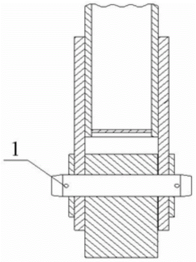
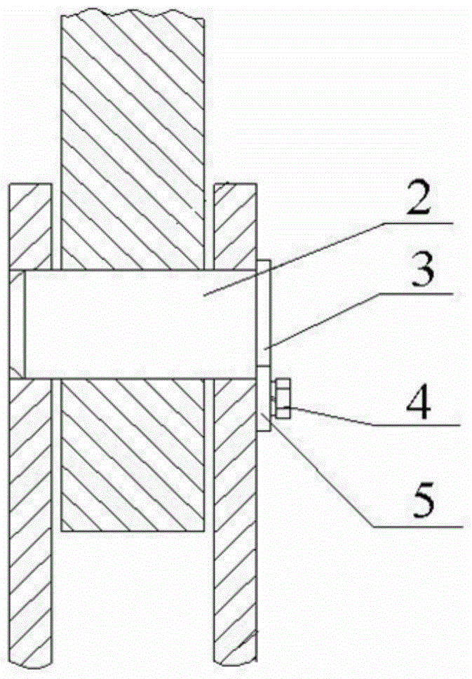
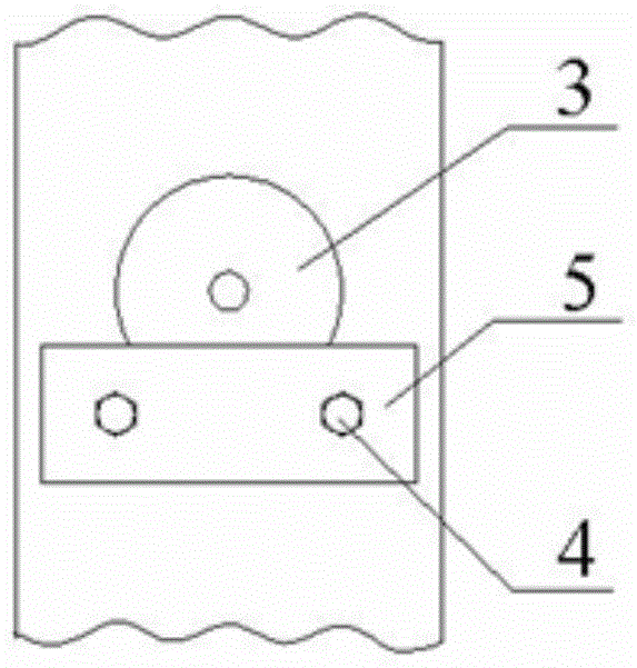
[0021] like Figure 4 and Figure 5 As shown, a pin connection structure, including a headless pin 1 that can be installed in the connector, pin holes are opened at both ends of the headless pin 1, and also includes a The stop sleeve 8 is limited in the axial direction of the pin shaft. The stop sleeve 8 is connected with the headless pin shaft 1 through the vertical pin 12. One end of the vertical pin 12 has a pin hole, and the hole end of the vertical pin 12 is equipped with a lock for fixing. live in institutions.

[0022] The stop sleeve 8 is set on the shaft end of the headless pin shaft 1, and the stop sleeve 8 has a mounting hole for installing the vertical pin 12, and the vertical pin 12 passes through the installation hole on the stop sleeve 8 and the pin shaft on the headless pin shaft 1 Fix the stop sleeve 8 on the headless pin shaft 1 after the hole, install ...


PUM


Abstract

The invention discloses a pin shaft connection structure, which belongs to the field of component connection devices, and comprises a headless pin shaft (1) which can be installed in a connecting piece. Both ends of the headless pin shaft (1) are provided with pin shaft holes, and further includes The stop sleeve (8) that can be fitted on the headless pin (1) is used for the axial limit of the pin shaft. The stop sleeve (8) is connected with the headless pin (1) through the vertical pin (12), and the vertical pin ( One end of 12) has bearing pin hole, and the perforated end of vertical pin (12) is equipped with fixing locking mechanism. The pin shaft connection structure installs a retaining sleeve on the shaft end of the headless pin, and through the rotating operation of the retaining sleeve, the vertical pin can conveniently connect the retaining sleeve and the headless pin in series, and the installation efficiency is high; The locking structure is installed at the opening end to effectively fix the vertical pin, avoiding the movement of the vertical pin to affect the position of the headless pin shaft, and at the same time, it can effectively limit the wear or shearing of the cotter pin, making the connection safer and more reliable.

Description

technical field [0001] The invention relates to a pin shaft connection structure, which belongs to the field of component connection devices. Background technique [0002] At present, there are generally two ways to connect the metal structure of tower cranes, high-strength bolt connection or pin connection. Many tower crane components use pin connection. Commonly used pin connections include cotter pin type and shaft end baffle type. like figure 1 In the cotter pin type pin connection shown, after the headless pin 1 is driven into the connection part, the two ends of the pin are directly locked with cotter pins. This connection method can easily limit the axial movement of the pin shaft, but the cotter pin The structural stability is weak, and after a long time of use, it is easy to wear, cut or fall off; figure 2 In the shaft end baffle type pin connection shown, one end of the shaft shoulder pin 2 is a shaft shoulder 3, and there is a notch for matching with the baffle...

Claims


Application Information

Patent Timeline
Patent Type & Authority Patents(China)
IPC IPC(8): F16B21/14F16B21/10
CPCF16B21/10F16B21/12F16B21/14
Inventor 王建军米成宏刘振王磊李海峰
Owner XUZHOU CONSTR MACHINERY
Why Eureka
Try Eureka