


Quick Research
Generate reliable direction feasibility study reports for your R&D in just a few steps.

Technical Q&A
Discover and master advanced knowledge NOW. Basics, ideas, possibilities, all at once.

Find Solutions
As an expert in R&D theories, this can generate solutions to your technical problems instantly.

Evaluate Feasibility
Analyze your overall solution with one click, know your potential R&D risks in advance.

Monitor Landscape
Get weekly tech updates, stay abreast of the latest tech innovations and key insights.
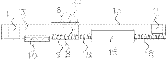
Winding sheet high frequency welding feeding device
A feeding device and high-frequency welding technology, which is applied in the field of high-frequency welding feeding devices around sheets, can solve the problems of unfavorable heat transfer area and heat transfer efficiency, etc., to extend the heat transfer path, improve heat transfer efficiency, and increase heat transfer efficiency. The effect of hot area
- Summary
- Abstract
- Description
- Claims
- Application Information
AI Technical Summary
Problems solved by technology
Method used
Image


Examples
Embodiment 1
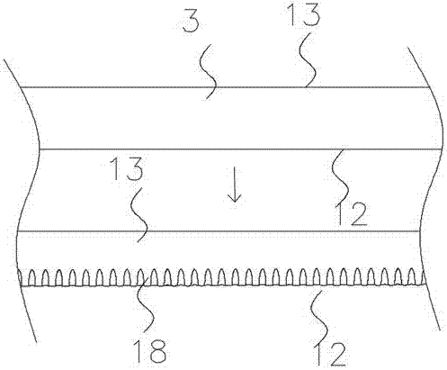
[0029] A sheet-wound high-frequency welding feeding device, including a feeding pair of rollers 1, a high-frequency magnetic induction heating coil, a rolling pair of rollers, a cooling assembly, and a discharging pair of rollers 2 arranged in sequence along the flow direction. The belt 3 is input from the feed pair of rolls 1, and is sequentially processed on the high-frequency magnetic induction heating coil, the rolling pair of rolls, and the cooling assembly, and then output from the discharge pair of rolls 2; The roll 4 and the lower hot rolling roll 5, the upper hot rolling roll 4 and the lower hot rolling roll 5 all include a flat section 6 that cooperates with the welding side edge 13 of the winding sheet material strip and a rolling section that cooperates with the heat exchange side edge 12 of the winding sheet material strip Section 7, the rolling section 7 includes rolling convex ribs 8 and rolling concave ribs 9 uniformly distributed around the upper hot rolling ro...
Embodiment 2
[0035]Further optimization of Example 1, the rolling concave rib 9 and the rolling convex rib 8 are arranged at intervals on the upper hot rolling roll 4 and the lower hot rolling roll 5, and the thickness of the rolling rolling rib 8 is along the starting end of the rolling section 7 It gradually increases to the outer end, and the depth of the rolling rib 8 gradually increases along the starting end of the rolling section 7 to the outer end.
[0036] The surfaces of the rolling concave ribs 9 and the rolling convex ribs 8 are in a smooth transition shape and are connected to each other to form a wavy rolling surface around the upper hot rolling roll 4 and the lower hot rolling roll 5 .
[0037] Limiting ribs 14 are provided at the ends of the upper hot rolling roll 4 and the lower hot rolling roll 5 close to the welding side 13 of the winding strip. The limiting rib 14 is annular, and the protrusion is arranged on the ends of the upper hot roll 4 and the lower hot roll 5 clo...
PUM
 Abstract
Description
Claims
Application Information
 - R&D Engineer
- R&D Manager
- IP Professional
- Industry Leading Data Capabilities
- Powerful AI technology
- Patent DNA Extraction
Browse by: Latest US Patents, China's latest patents, Technical Efficacy Thesaurus, Application Domain, Technology Topic, Popular Technical Reports.
© 2024 PatSnap. All rights reserved.Legal|Privacy policy|Modern Slavery Act Transparency Statement|Sitemap|About US| Contact US: help@patsnap.com