
Myocardial ablation device

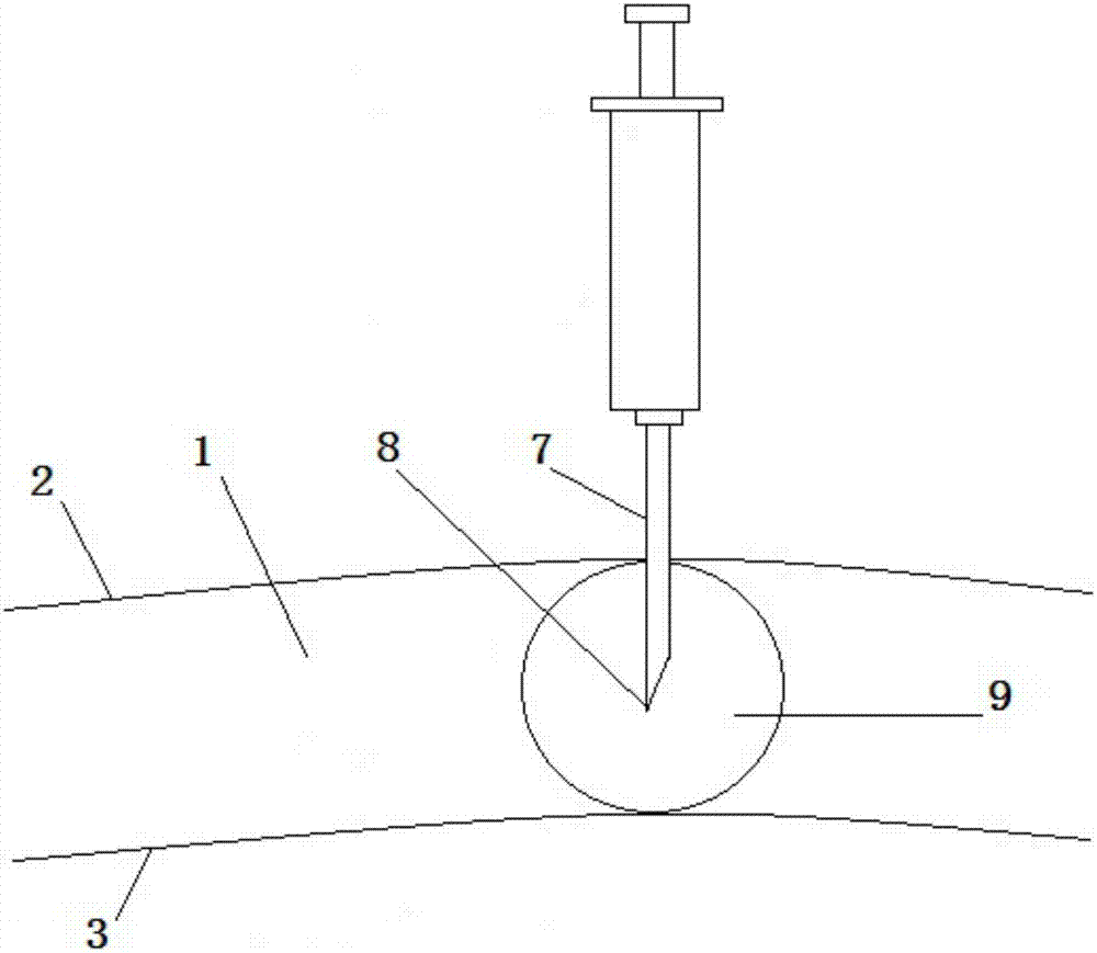
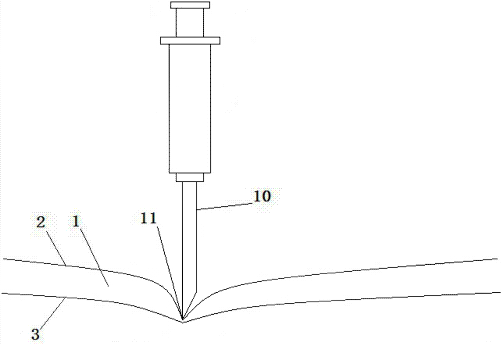
A myocardial and core technology, applied in the field of myocardial ablation devices, can solve the problems of high cost, inability to develop in hospitals, difficult myocardial tissue, etc., and achieve the effects of low cost, wide range of indications and applications, and simple operation.

Pending Publication Date: 2018-04-06
SINUS MEDICAL TECH
View PDF0 Cites 3 Cited by
  • Summary
  • Abstract
  • Description
  • Claims
  • Application Information

AI Technical Summary

Problems solved by technology

[0004] However, the bipolar radiofrequency ablation pen currently used for linear ablation in atrial fibrillation surgery is attached to the epicardium to release radiofrequency energy, and it is difficult to form transmural damage to thicker myocardial tissue, especially for hypertrophic In patients with cardiomyopathy, it is more difficult for these radiofrequency ablation pens to cause damage deep in the ventricular wall, so some atrial fibrillation and most ventricular arrhythmias are less effective for treatment
Moreover, the existing bipolar radiofrequency ablation pen cannot map whether there is still electrical activity or conduction at the ablation site after the ablation is completed, so that the surgical effect cannot be verified during the operation, leaving certain hidden dangers for the recurrence of arrhythmia
In addition, the bipolar radiofrequency ablation pens currently in use are all imported, with complex structures, high cost, and a series of supporting equipment such as radiofrequency energy generators, which makes the surgical treatment of atrial fibrillation expensive, and makes it impossible for some hospitals to carry out this procedure. treat

Method used


Image

  • Myocardial ablation device
  • Myocardial ablation device
  • Myocardial ablation device

Examples


Embodiment Construction

[0041] definition

[0042] Distal: In this specification, when referring to "distal" when describing the device of the present invention, the term refers to the side relatively far from the user.

[0043] Proximal: In this specification, when referring to the "proximal side" when describing the device of the present invention, the term refers to the side relatively close to the user.

[0044] Distal end: In this specification, when referring to "distal end" when describing the device of the present invention, the term generally refers to the end relatively far from the user or the body (eg handle) of the device of the present invention.

[0045] Proximal end: In this specification, when referring to "proximal end" when describing the device of the present invention, the term generally refers to the end relatively close to the user or relatively close to the body (eg handle) of the device of the present invention.

[0046] Sagittal plane: The plane passing through the vertical...


PUM


Abstract

The invention relates to a myocardial ablation device capable of ablating myocardial tissues point by point. The myocardial ablation device comprises a handle part, an outer sleeve and a core part, wherein the handle part comprises a shell which is distributed on the proximal side of the myocardial ablation device, a near end accommodating the outer sleeve and a near end of the core part; a negative pressure attraction pipeline is arranged in the handle part, and a negative pressure connecting hole formed in the negative pressure attraction pipeline is used for connecting a vacuum generation device; the outer sleeve is provided with a first hollow pipeline and a second hollow pipeline, the near end of the first hollow pipeline is connected with a negative pressure suction pipeline, the farend of the first hollow pipeline is provided with a negative pressure sucker which comprises a side wall and one or more negative pressure suction openings; the core part is provided with a third hollow pipeline, the near end of the core part is provided with a liquid injection pipeline, a liquid injection connector and a mobile control part, and the far end of the core part is provided with a tip end; the liquid injection pipeline is communicated with the third hollow pipeline, and the near end of the liquid injection pipe is the liquid injection connector; and a mobile control part is distributed on the core part and is used for controlling the core part to move along the second hollow pipeline of the outer sleeve.

Description

technical field [0001] The present invention relates to a surgical instrument for treating and mapping arrhythmia, in particular to a myocardial ablation device capable of ablation of myocardial tissue point by point, preferably, the myocardial ablation device can also map electrocardiogram point by point Activity. Background technique [0002] Arrhythmia is a series of diseases in which the heart loses its inherent rhythm due to various reasons, and its incidence rate is high and it is extremely harmful to health. For example, the most common persistent arrhythmia in clinical practice is called atrial fibrillation (abbreviated as atrial fibrillation). It is caused by various pathogenic factors that lead to abnormal changes in the electrophysiological properties of atrial myocytes, causing rapid and irregular contractions of the atria and ventricles. As a result, patients will have symptoms such as palpitations, shortness of breath, and fatigue, and increase the incidence o...

Claims


Application Information

Patent Timeline
Patent Type & Authority Applications(China)
IPC IPC(8): A61M31/00A61B17/34
CPCA61M31/00A61B17/3417A61B2017/3454A61M2210/125A61M2230/04A61M2210/005
Inventor 刘兴鹏毛俊张明东张明芳
Owner SINUS MEDICAL TECH
Learn More