Eureka AIR delivers breakthrough ideas for toughest innovation challenges, trusted by R&D personnel around the world.

Manufacturing process of sealing cutter for heat shrinkage film cloth roll packaging machine

A production process and packaging machine technology, which is applied in the production process field of sealing and cutting knives for heat-shrinkable film cloth roll packaging machines, can solve the problems of sealing effect, high cost, and difficult assembly, so as to ensure cleanliness and aesthetics, temperature The effect of high accuracy and saving mold opening cost

Inactive Publication Date: 2018-04-03
合肥果成科技有限公司
View PDF6 Cites 0 Cited by
  • Summary
  • Abstract
  • Description
  • Claims
  • Application Information

AI Technical Summary

Problems solved by technology

[0002] Chinese invention patent 201210014583.4 discloses a combined sealing and cutting knife device for packaging machines, including a knife seat, two sealing knives and a cutting knife, a heating tube is installed on the knife seat, and two pieces are installed at the lower end of the knife seat Sealing knife, a cutter is installed between the two sealing knives. The sealing and cutting knife with this structure has the following problems: First, the assembly is difficult. When assembling the two sealing knives, it is difficult to ensure that the end faces of the two sealing knives are in the The same plane, which affects the sealing effect; secondly, in order to ensure that the cutter is smoothly assembled between the two sealing knives, the end face of the sealing knife and the cutter should be provided with a concave arc, so when the cutter is installed Finally, there will be a concave gap between the cutting knife and the sealing knife, and the film filaments generated during the working process will be easily embedded in the concave gap. When cutting next time, the embedded film filaments will stick to the cutting seal , thereby affecting the cleanliness and beauty of the seal; thirdly, the temperature of the heat pipe on the knife seat is difficult to detect for the combined structure of the sealing knife, and at the same time, it is often difficult to detect the temperature of the heating pipe on the knife seat due to the different materials selected for the knife seat, sealing knife and cutter. The accurate sealing and cutting temperature is detected, but the cutting temperature of the plastic film is strict. If the temperature is difficult to control, it will seriously affect the sealing and cutting effect. Fourth, the combined structure of the sealing and cutting knife needs to open at least 3 kinds of molds, and the cost is high

Method used


Image

  • Manufacturing process of sealing cutter for heat shrinkage film cloth roll packaging machine

Examples


Embodiment 1

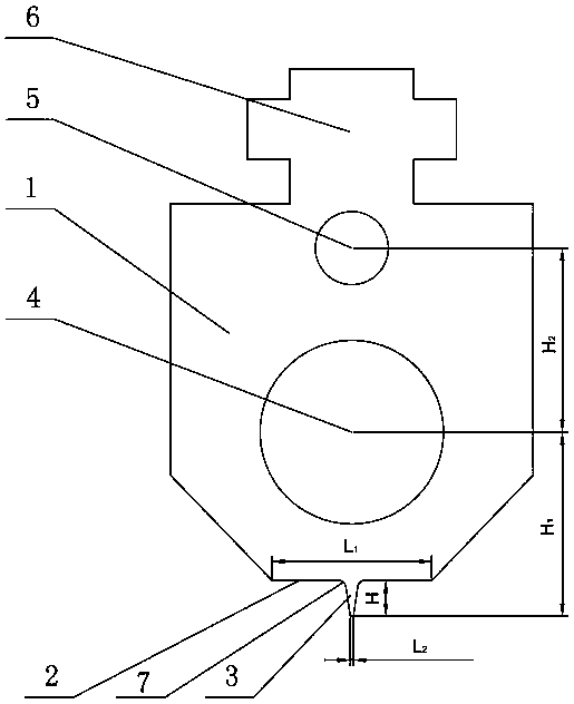
[0011] Embodiment 1: As shown in Figure 1, a manufacturing process of a sealing and cutting knife for a heat-shrinkable film cloth roll packaging machine, including a base 1, the lower end surface of the base 1 is a sealing surface 2, and the sealing surface 2 is a plane. The sealing surface 2 is integrally provided with a raised rib 3, which has the same length as the sealing surface 2 and divides the sealing surface 2 into two parts with the same width; the base 1 is provided with a heat pipe installation hole 4 and a thermocouple The installation hole 5, the center of the heat pipe installation hole 4 and the center line of the thermocouple installation hole 5 coincide with the central axis of the rib 3, and the vertical distance H1 from the center of the heat pipe installation hole 4 to the top of the rib 3 is the same as that of the thermocouple installation The vertical distance H2 from the center of the hole 5 to the top of the rib 3 is equal.

[0012] In this specific ...


PUM


Abstract

The invention discloses a sealing cutter for a heat shrinkage film cloth roll packaging machine. The cutter is characterized by comprising a base, the lower end face of the base is a sealing face, thesealing face is a plane, a convex rib is integrally arranged on the sealing face, the convex rib is equal to the sealing face in length, the sealing face is divided into two parts with the same width, a heating pipe mounting hole and a thermocouple mounting hole are formed in the base, the connecting line of the centre of the heating pipe mounting hole and the center of the thermocouple mountinghole coincides with the central axis of the convex rib, and the vertical distance between the center of the heating pipe mounting hole and the top end of the convex rib is equal to the vertical distance between the center of the thermocouple mounting hole and the top end of the convex rib. The sealing cutter has the beneficial effects of being simple in structure, easy to assemble, low in cost andgood in sealing cutting effect.

Description

technical field [0001] The invention relates to a sealing and cutting device for a heat-shrinkable film packaging machine, in particular to a manufacturing process of a sealing and cutting knife for a heat-shrinkable film cloth roll packaging machine. Background technique [0002] Chinese invention patent 201210014583.4 discloses a combined sealing and cutting knife device for packaging machines, including a knife seat, two sealing knives and a cutting knife, a heating tube is installed on the knife seat, and two pieces are installed at the lower end of the knife seat Sealing knife, a cutter is installed between the two sealing knives. The sealing and cutting knife with this structure has the following problems: First, the assembly is difficult. When assembling the two sealing knives, it is difficult to ensure that the end faces of the two sealing knives are in the The same plane, which affects the sealing effect; secondly, in order to ensure that the cutter is smoothly asse...

Claims


Application Information

Patent Timeline
Patent Type & Authority Applications(China)
IPC IPC(8): B65B61/10
CPCB65B61/10
Inventor 李质玉
Owner 合肥果成科技有限公司
Why Eureka
Eureka Blog
Learn More