A hydrostatic test plugging valve

A technology of hydraulic test and valve blocking, which is applied in the direction of pipes/pipe joints/fittings, mechanical equipment, pipe components, etc., which can solve the problems of long time-consuming disassembly and assembly of blocked valves, difficulty in disassembly and assembly of blocked valves, and long production cycle. , to achieve the effect of simple and quick disassembly and assembly, difficult assembly, and small installation space requirements

Active Publication Date: 2018-05-15
NANTONG POWER STATION VALVE
View PDF5 Cites 0 Cited by
  • Summary
  • Abstract
  • Description
  • Claims
  • Application Information

AI Technical Summary

Problems solved by technology

[0003] The disadvantages of this type of plugging valve are: 1. When the valve body and bonnet are castings, it needs to be molded and cast, and the production cost is high and the cycle is long; 2. When the valve body and bonnet are forgings, the blank size is large and the production The cost is high, and at the same time, the processing of free forging blanks is difficult, the amount of machining and cutting is large, and the production cycle is long; 3. The sealing surface of the valve body needs to be surfacing with stainless steel or hard alloy steel, which has certain requirements for the manufacturing level of the manufacturer, and increases the number of products 4. It is difficult to disassemble and assemble the plugging valve, and it takes a long time to disassemble and assemble the plugging valve, which brings more inconvenience to users; 5. When installing the plugging valve, it is necessary to determine the medium during the pressure test The flow direction and the flow direction of the medium during normal operation, the flow direction of the two states needs to be determined according to the installation position of the plugging valve, sometimes the flow direction of the medium in the two states is the same, and sometimes it is opposite, so whether it is initial installation or assembly during use, more professional technicians are required. Guidance; 6. It is difficult to control and detect whether the plugging valve has been installed correctly when it is installed in the blocking plate. Once the plugging valve is found to fail to shut off the system pipeline during the hydraulic test, it is necessary to stop the test, re-disassemble and check, and then assemble the plugging valve , at the same time, the user needs to re-pressurize the system, which will cause great economic losses to the user, and the test period will be prolonged

Method used


Image

  • A hydrostatic test plugging valve
  • A hydrostatic test plugging valve
  • A hydrostatic test plugging valve

Examples


Embodiment

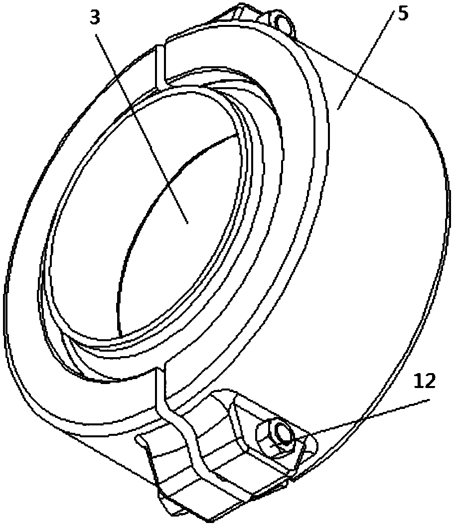
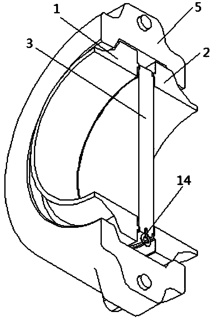
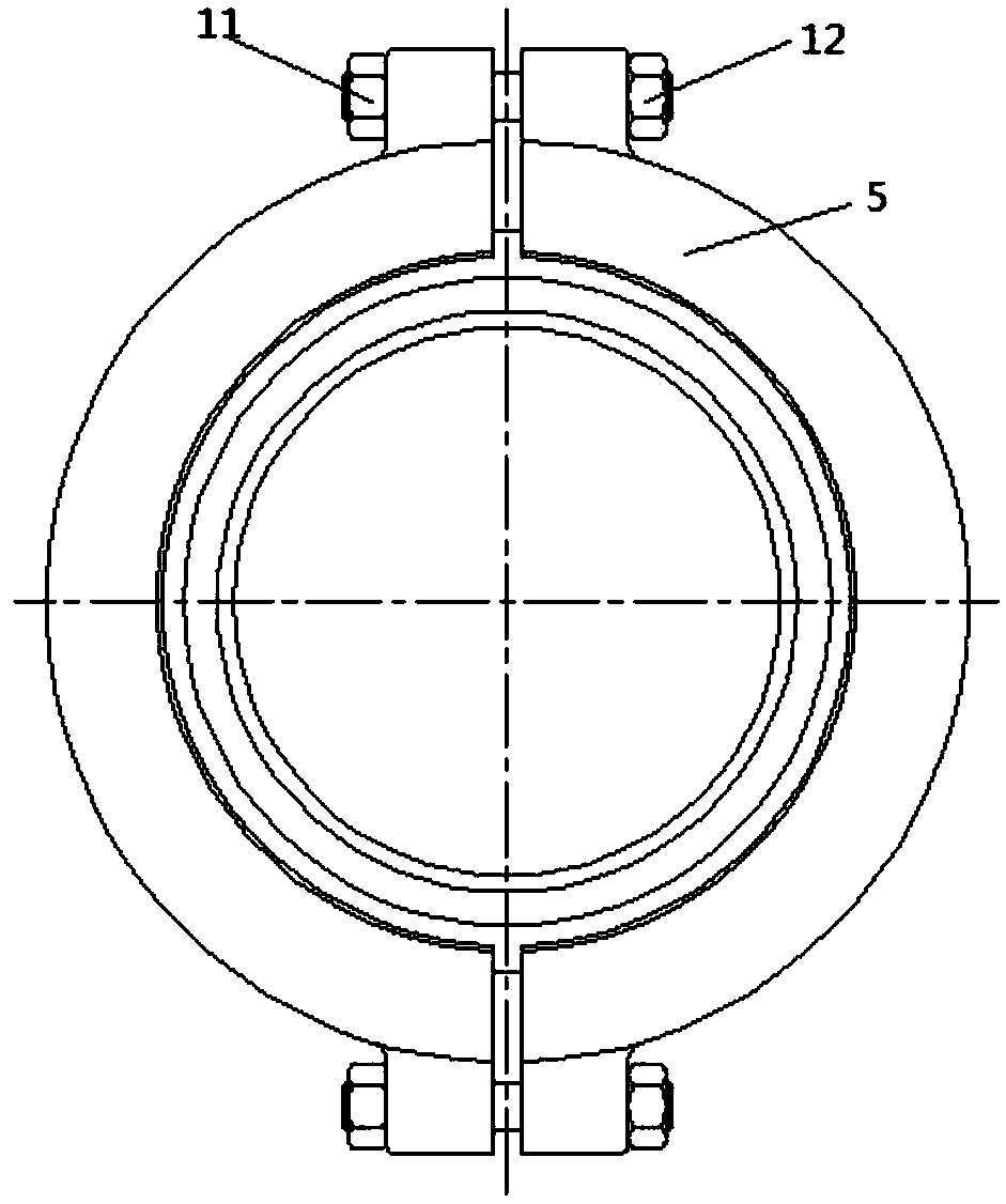
[0036] like Figure 1 to Figure 10 As shown, a plugging valve for a hydraulic test of the present invention includes a left flange 1, a right flange 2, a connecting mechanism and a clamp 5, and the size of the left flange 1 and the right flange 2 and the shape are the same, the connecting mechanism is arranged between the left flange 1 and the right flange 2, and the left flange 1 and the right flange 2 are embedded in the clamp 5 Inside, the connecting mechanism is a blocking plate 3 or a guide tube 4, the left flange 1 is provided with a groove I, and the right flange 2 is provided with a groove II, and the connecting mechanism and the The groove I of the left flange 1 is matched with the groove II of the right flange 2.

[0037] Further, the groove I on the left flange is set as an L-shaped groove I6, and the groove II on the right flange is set as an L-shaped groove II7.

[0038] Further, the connecting mechanism is a blocking plate 3, and the hydraulic test blocking val...


PUM


Abstract

The invention relates to the field of valves, in particular to a hydraulic testing plug valve. The hydraulic testing plug valve comprises a left side flange, a right side flange, a connecting mechanism and a clamp. The connecting mechanism comprises a plug board or a flow guide pipe; the left side flange and the right side flange are provided with a groove I and a groove II correspondingly; a boss I and a boss II are arranged on the periphery of the plug board and the outer wall periphery of the flow guide pipe correspondingly; and the flow guide pipe and the plug board are switched between an operation state and a pressure testing state. Under different states, the flow guide pipe or the plug board is arranged between the left side flange and the right side flange; the two sides of the boss I and the two sides of the boss II are matched with the groove I and the groove II correspondingly; a groove III is formed in the clamp; the left side flange and the right side flange are embedded into the groove III of the clamp; the left side flange and the right side flange are clamped through the clamp, and meanwhile the plug board or the flow guide pipe is clamped at the same time. The hydraulic testing plug valve is simple in structure, reliable in fastening, easy, safe and convenient to operate, high in sealing performance, capable of being mounted at any position of a system, free of flowing direction requirements, capable of being mounted in any direction and low in manufacturing cost.

Description

technical field [0001] The invention relates to the technical field of valves, in particular to a hydrostatic test plugging valve. Background technique [0002] The hydraulic test plugging valve is installed in the pipeline system that needs to be tested. When pressing, place the blocking plate, support plate and top column in the valve body, pre-tighten the blocking plate with the top column, and complete the valve assembly, and then use the medium pressure during the pipeline pressure test to make the blocking plate and the valve body form a sealing pair, In order to achieve the purpose of segmental pressure test of the system pipeline, after the pressure test is completed, disassemble the valve, take out the blocking plate, support plate and top column, put them into the diversion tube, and press the diversion tube with the pressure plate to prevent the diversion tube from being damaged. As the system medium pressure fluctuates in the valve, the valve assembly is complet...

Claims


Application Information

Patent Timeline
Patent Type & Authority Patents(China)
IPC IPC(8): F16L55/11G01M3/02
CPCF16L55/1108G01M3/02
Inventor 朱东升孟新凌朱洪根
Owner NANTONG POWER STATION VALVE
Why Eureka
Try Eureka