Composite conductive copper bar

A technology of composite conductive and copper bars, which is applied in the field of electrical conductors, can solve the problems of large occupied space, large partition surface of composite conductive copper bars, inconvenient dust cleaning, etc., and achieve the effect of easy cleaning and easy replacement

Inactive Publication Date: 2018-03-30
JIANGSU HUALIAN ELECTRIC POWER EQUIP
View PDF0 Cites 1 Cited by
  • Summary
  • Abstract
  • Description
  • Claims
  • Application Information

AI Technical Summary

Problems solved by technology

[0004] The purpose of the present invention is to provide a composite conductive copper bar, to solve the existing composite conductive copper bar proposed in the above-mentioned background technology, when in use, the connection between the composite conductive copper bars is fixedly connected by nuts in a superimposed manner, so that The connection method makes the composite conductive copper bar have a larger partition surface during the connection process, which takes up more space when used as a whole, and the way of superposition is not good enough to make the composite conductive copper bar have an overall visual sense. The heat-shrinkable sleeve of the conductive copper bar is protected in the space of the composite conductive copper bar, so that a large amount of dust falls on the outer surface of the heat-shrinkable sleeve, and the dust is inconvenient to clean up.

Method used


Image

  • Composite conductive copper bar
  • Composite conductive copper bar
  • Composite conductive copper bar

Examples


Embodiment Construction

[0015] The following will clearly and completely describe the technical solutions in the embodiments of the present invention with reference to the accompanying drawings in the embodiments of the present invention. Obviously, the described embodiments are only some, not all, embodiments of the present invention. Based on the embodiments of the present invention, all other embodiments obtained by persons of ordinary skill in the art without making creative efforts belong to the protection scope of the present invention.

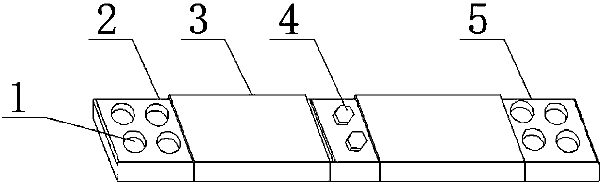
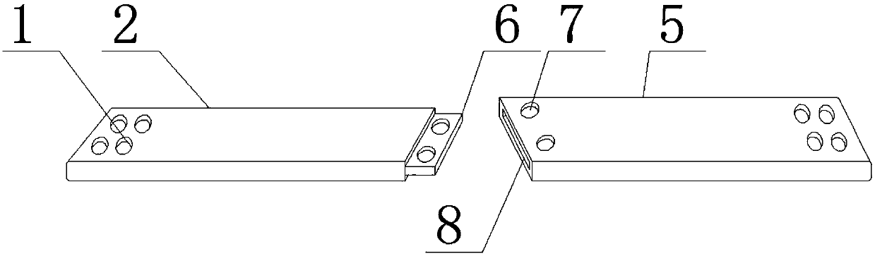
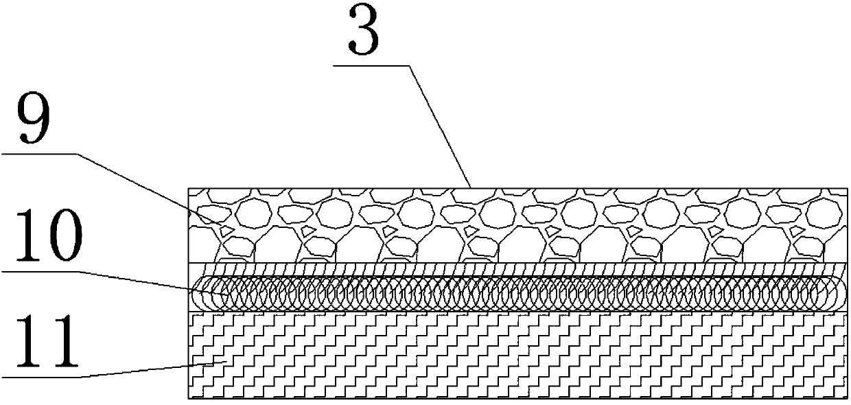
[0016] see figure 1 , figure 2 with image 3 , the present invention provides a technical solution: a composite conductive copper bar, including a first copper bar 2, a connecting bolt 4 and a second copper bar 5, one end of the first copper bar 2 is provided with a fixing hole 1, the first copper bar The other end of 2 is provided with a connecting plate 6, the outer surface of the first copper bar 2 is provided with a protective sleeve 3, and the connecti...


PUM


Abstract

The invention discloses a composite conductive copper bar, comprising a first copper bar, connecting bolts and a second copper bar, one end of the first copper bar is provided with a fixing hole, and the other end of the first copper bar is provided with a connecting plate, the outer surface of the first copper bar is provided with a protective sleeve, the connection position between the second copper bar and the connecting plate is provided with a connecting groove, and the connecting bolts between the second copper bar and the first copper bar Fixedly connected, the connection position between the connecting bolt and the second copper bar is provided with a connection hole, the bottom end of the protective sleeve is provided with a heat shrinkable sleeve, and the top of the heat shrinkable sleeve is provided with a Velcro, so The top of the Velcro is provided with a dust-proof pad; by providing a connection plate and a connection groove at the connection position between the composite conductive copper bars, the connection method using the slot is compared with the traditional connection method, reducing the distance between the composite conductive copper bars. The partition surface of the inter-connection makes the connection between the composite conductive copper bars more integrated.

Description

technical field [0001] The invention belongs to the technical field of electric conductors, and in particular relates to a composite conductive copper bar. Background technique [0002] Copper bars, also known as copper bus bars or copper bus bars, are made of copper and have a rectangular or chamfered (rounded) rectangular long conductor section (now generally use rounded copper bars to avoid tip discharge). The circuit plays the role of transmitting current and connecting electrical equipment. Copper bars are widely used in electrical equipment, especially complete sets of power distribution devices; generally, copper bars are used for U, V, W phase bus bars and PE bus bars in power distribution cabinets; copper bars are generally marked in use With matching color letters or painted with matching color paint, U-phase copper bars are painted with "yellow" color, V-phase copper bars are painted with "green" color, W-phase copper bars are painted with "red" color, PE bus bar...

Claims


Application Information

Patent Timeline
Patent Type & Authority Applications(China)
IPC IPC(8): H01R11/01H01R11/09H01R4/34H01B7/17
CPCH01R11/01H01B7/17H01R4/34H01R11/09
Inventor 鄂友亮何伯成陈晓海
Owner JIANGSU HUALIAN ELECTRIC POWER EQUIP
Why Eureka
Try Eureka