Connecting and supporting structure of multifunctional hydraulic control system

A hydraulic control system and support structure technology, applied in wind power generation, components with teeth, transmission devices, etc., can solve the problems of sharply increased development costs and longer design and development cycles, and achieve improved energy transfer efficiency and fixed connections and the effect of simple assembly process and increased usable space

Pending Publication Date: 2022-05-31
SHAANXI FAST GEAR CO
View PDF0 Cites 0 Cited by
  • Summary
  • Abstract
  • Description
  • Claims
  • Application Information

AI Technical Summary

Problems solved by technology

Make the design and development cycle longer, and the development cost increases sharply

Method used


Image

  • Connecting and supporting structure of multifunctional hydraulic control system
  • Connecting and supporting structure of multifunctional hydraulic control system
  • Connecting and supporting structure of multifunctional hydraulic control system

Examples


Embodiment 1

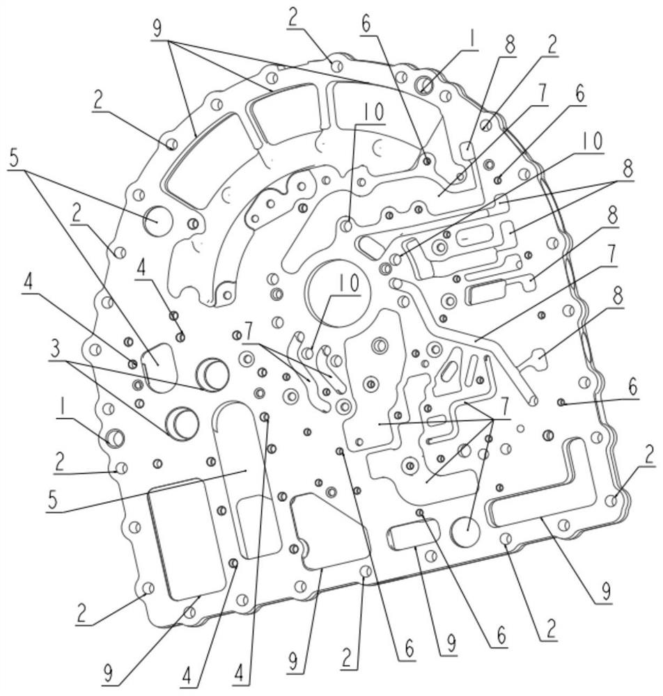
[0037] see Figure 1 to Figure 6 , the features required on the hydraulic system connection support structure are all machined according to the specific size requirements, and the four positioning pins 21 are respectively installed on the two sides of the connection support device to the two sides of the connection support structure. In the fixing pin hole 1 connected with the gearbox casing and the torque converter casing, ensure that the connection support structure is stably and accurately fixed to the upper end surface of the hydraulic automatic transmission casing, providing a stable foundation for the subsequent layout of different subsystems. platform. Install the sealing device 22 on the end face of the connecting support structure connecting the hydraulic control system module and the power input device of the hydraulic system to ensure that there is no misalignment between the through holes of the power medium, and ensure that the hydraulic control system module and ...

Embodiment 2

[0046] Such as Figure 7 Shown, be another kind of embodiment of the present invention, embodiment 2 is similar in structure to embodiment 1, and its difference is:

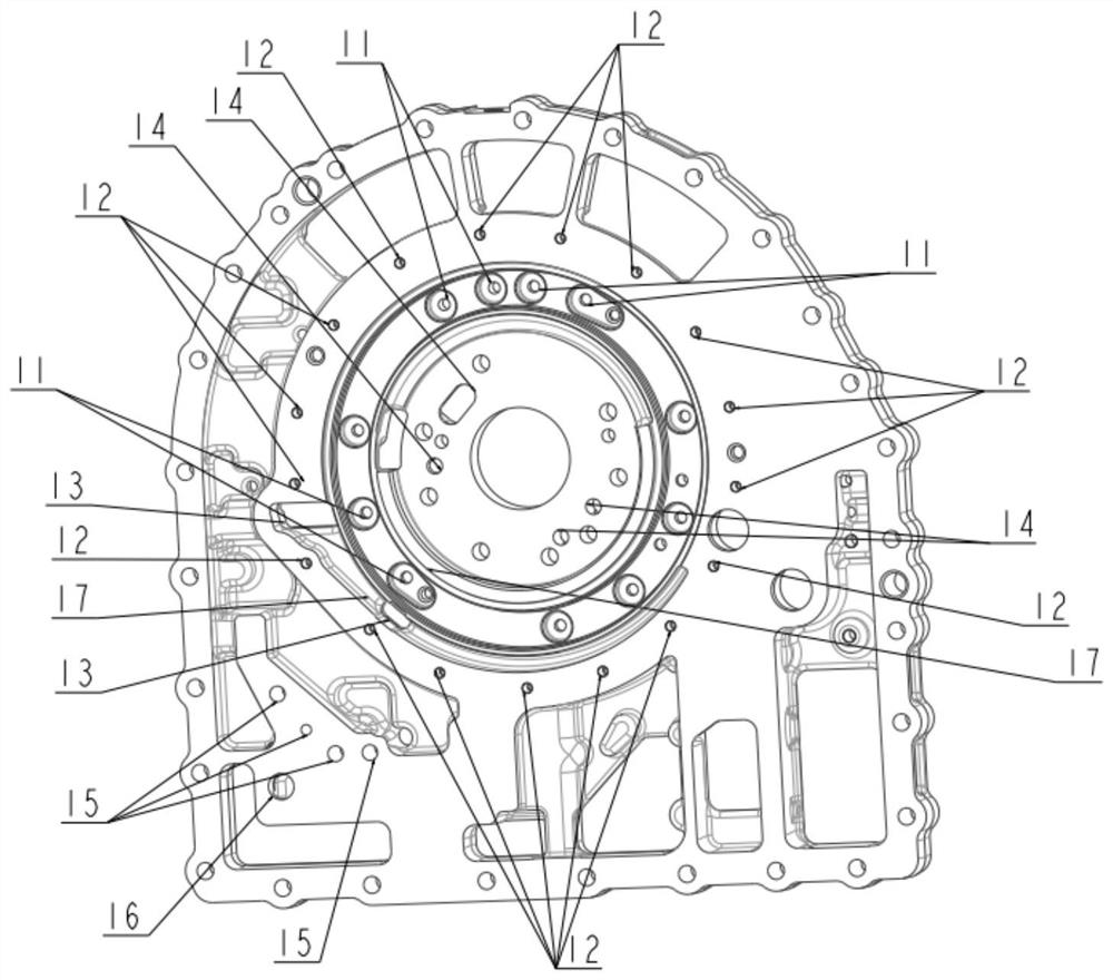
[0047]The features required for the connection support structure of the hydraulic system are all machined according to the specific size requirements, and 11 through holes for fasteners connected to the fixing parts of the hydraulic deceleration system can be omitted. The machining steps of the fastener threaded holes 12 of the shell and the three through holes 13 of the power medium channel connecting the hydraulic deceleration system device reduce the machining process, improve the production efficiency of the parts, and reduce a certain cost.

[0048] Then follow the steps of Embodiment 1 to assemble to the hydraulic torque converter guide wheel seat 29 and the power medium distribution device 28, and the hydraulic deceleration system device 27 and its accessories are no longer used in this embodiment. At thi...


PUM


Abstract

The invention discloses a connecting and supporting structure of a multifunctional hydraulic control system, which is characterized in that a hydraulic control module, a hydraulic system power input device, a hydraulic deceleration system device, a hydraulic torque converter, even a starting motor and other sub-functional systems are compactly assembled in a limited internal space of a transmission by forming various holes and medium channels; on the premise that the functions of the gearbox assembly are normally achieved, the size and the weight of the gearbox are greatly reduced. And meanwhile, the difficulty of the assembly process is reduced, and the cost of the gearbox assembly is reduced. The number of related auxiliary parts is small, so that the fixed connection and assembly process of the hydraulic system control module of the hydraulic automatic gearbox becomes simple, and later disassembly and maintenance of products are facilitated; the energy loss of the power medium in the transmission process along the power medium channel is reduced, and the overall energy transmission efficiency of the gearbox hydraulic system is improved.

Description

technical field [0001] The invention belongs to the field of automobile transmissions, in particular to a connection support structure of a multifunctional hydraulic control system. Background technique [0002] In the field of commercial high-torque hydraulic automatic transmissions, the functions required for hydraulic automatic transmissions will be more than those in other fields. For example, it is necessary to connect hydraulic control system modules, hydraulic system power input devices, Sub-functional systems such as hydraulic deceleration system devices, different forms of power take-offs, hydraulic torque converters and even starter motors. Usually commercial high-torque hydraulic automatic transmissions can be used in harsh working environments in order to ensure the strength of parts. The size of each part is relatively large, but the installation space of the gearbox body is very limited. The traditional layout schemes are generally arranged in different parts ...

Claims


Application Information

Patent Timeline
Patent Type & Authority Applications(China)
IPC IPC(8): F16H41/24F16H57/023F16H57/021F16H57/02
CPCF16H41/24F16H57/023F16H57/021F16H57/02Y02E10/72
Inventor 杨瑄严鉴铂刘义张晨光赵伟伟丁斌严思敏冯浩成
Owner SHAANXI FAST GEAR CO
Why Eureka
Try Eureka