A timing detonation device and method
What is Al technical title?
Al technical title is built by PatSnap Al team. It summarizes the technical point description of the patent document.
A technology of detonating device and detonating circuit, which is applied in the direction of blasting, etc., can solve the problems of not being able to take into account the convenience of product use, low degree of automation, and low technical level, and achieve the effects of quick setting of timing time, high degree of automation, and simple operation
Inactive Publication Date: 2019-07-19
中国电波传播研究所 +1
View PDF4 Cites 0 Cited by
Summary
Abstract
Description
Claims
Application Information
AI Technical Summary
This helps you quickly interpret patents by identifying the three key elements:
Problems solved by technology
Method used
Benefits of technology
Problems solved by technology
my country's detonating equipment originated from the ignition technology for weapons. After decades of development, it has formed a relatively complete system integrating development, production, application, technical research and inspection and testing. However, the existing technical level of detonating equipment Low, under the premise of satisfying the safety, the convenience of use of the product cannot be taken into account, the operation is cumbersome, the degree of automation is low, the volume is bulky, and the function is single
Method used
Image
Click on the blue label to locate the original text in one second.
Reading with bidirectional positioning of images and text.
Examples
Embodiment 1
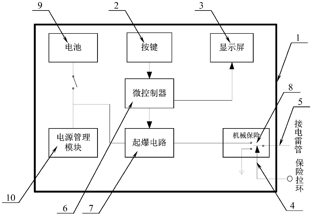
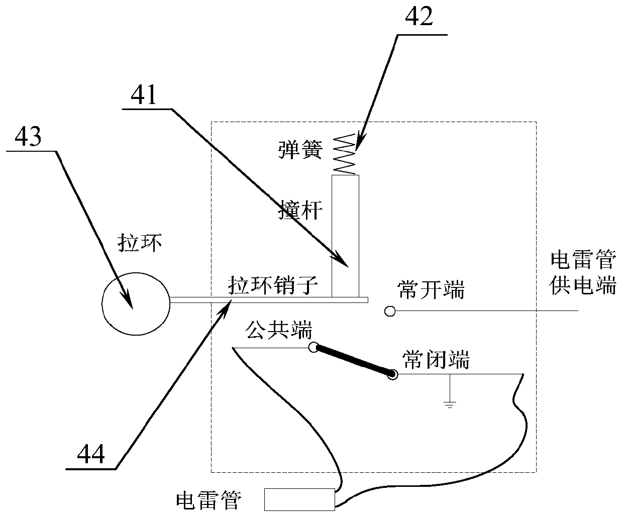
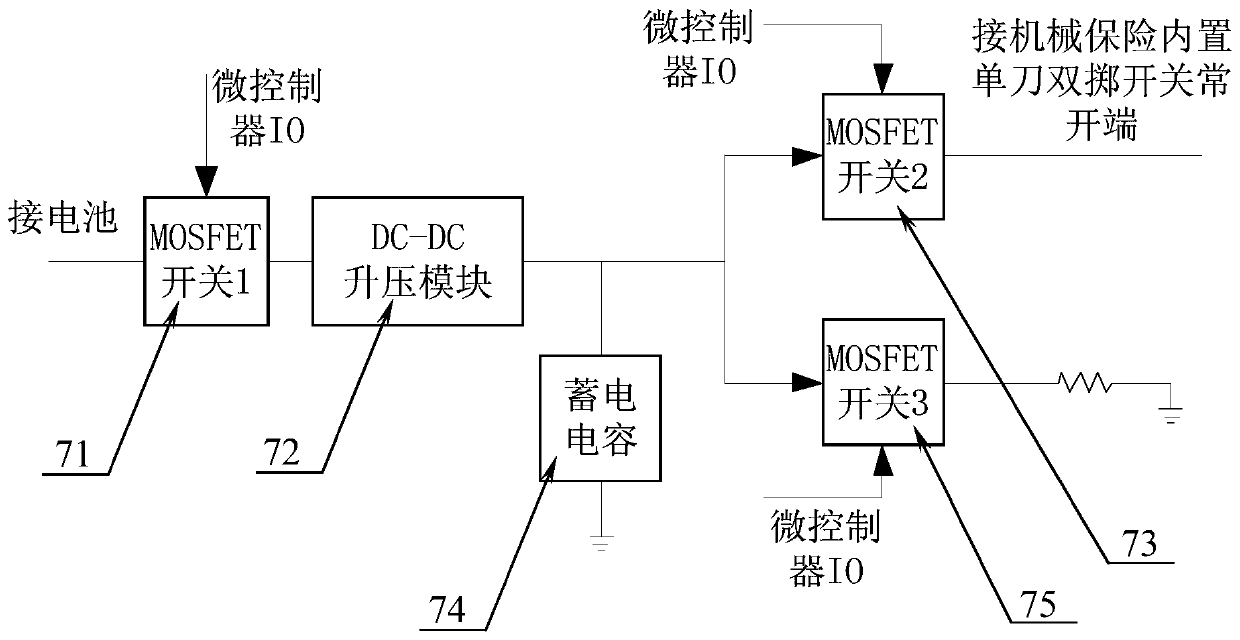
[0031] Example 1, such as figure 1 As shown, the present embodiment discloses a timing detonation device, the device includes a housing 1, on which a button 2, a display screen 3, a mechanical safety device 4 and an electric detonator socket 5 that can be connected to an electric detonator are arranged, The microcontroller 6 electrically connected with the above-mentioned button and display screen is installed in the housing, the detonation circuit 7 electrically connected with the above-mentioned microcontroller, the common end of the single-pole double-throw switch 8 is electrically connected with the above-mentioned electric detonator socket, the normally closed end is grounded, The normally open end is electrically connected to the detonating circuit. The paddle of the SPDT switch is connected to the common end and the normally closed end by default. When the mechanical insurance is released, the paddle is connected to the common end and the normally open end. The battery 9...
PUM
Abstract
The invention discloses a timing initiation device and method. The device comprises a shell; the shell is provided with a key, a display screen, a mechanical fuse and an electric detonator socket connected with an electric detonator; a microcontroller electrically connected with the key and the display screen and an initiation circuit electrically connected with the microcontroller are mounted inthe shell; a common end of a single-pole double-throw switch is electrically connected with the electric detonator socket, a normally closed end is grounded, and a normally open end is electrically connected with the initiation circuit; a poking piece of the single-pole double-throw switch is defaulted to communicate with the common end and the normally closed end; under the condition of relievingthe mechanical fuse, the poking piece communicates with the common end and the normally open end; and a battery supplies electricity to the device through a power supply management module. The timinginitiation device is small in size, low in weight, simple in operation, high in automation degree and convenient to carry; users can autonomously set the timing time; and the electric detonator is initiated to realize initiation after timing.
Description
technical field [0001] The invention belongs to the technical field of blasting equipment, in particular to a timing detonation device and method in the field. Background technique [0002] Detonating equipment is an important part of blasting equipment, and is widely used in transportation, mining, coal, petroleum, metallurgy, chemical industry, building materials, water conservancy, electric power, forestry, urban construction and other fields. my country's detonating equipment originated from the ignition technology for weapons. After decades of development, it has formed a relatively complete system integrating development, production, application, technical research and inspection and testing. However, the existing technical level of detonating equipment Low, under the premise of satisfying the safety, the convenience of use of the product cannot be taken into account, the operation is cumbersome, the degree of automation is low, the volume is bulky, and the function is ...
Claims
Application Information
Patent Timeline
Application Date:The date an application was filed.
Publication Date:The date a patent or application was officially published.
First Publication Date:The earliest publication date of a patent with the same application number.
Issue Date:Publication date of the patent grant document.
PCT Entry Date:The Entry date of PCT National Phase.
Estimated Expiry Date:The statutory expiry date of a patent right according to the Patent Law, and it is the longest term of protection that the patent right can achieve without the termination of the patent right due to other reasons(Term extension factor has been taken into account ).
Invalid Date:Actual expiry date is based on effective date or publication date of legal transaction data of invalid patent.