


Quick Research
Generate reliable direction feasibility study reports for your R&D in just a few steps.

Technical Q&A
Discover and master advanced knowledge NOW. Basics, ideas, possibilities, all at once.

Find Solutions
As an expert in R&D theories, this can generate solutions to your technical problems instantly.

Evaluate Feasibility
Analyze your overall solution with one click, know your potential R&D risks in advance.

Monitor Landscape
Get weekly tech updates, stay abreast of the latest tech innovations and key insights.
Energy storage device utilizing temperature difference self-driving loop
An energy storage device and self-driving technology, applied in the field of energy storage, can solve problems such as time and space mismatch, and achieve the effect of solving mismatch
- Summary
- Abstract
- Description
- Claims
- Application Information
AI Technical Summary
Problems solved by technology
Method used
Image


Examples
Embodiment 1
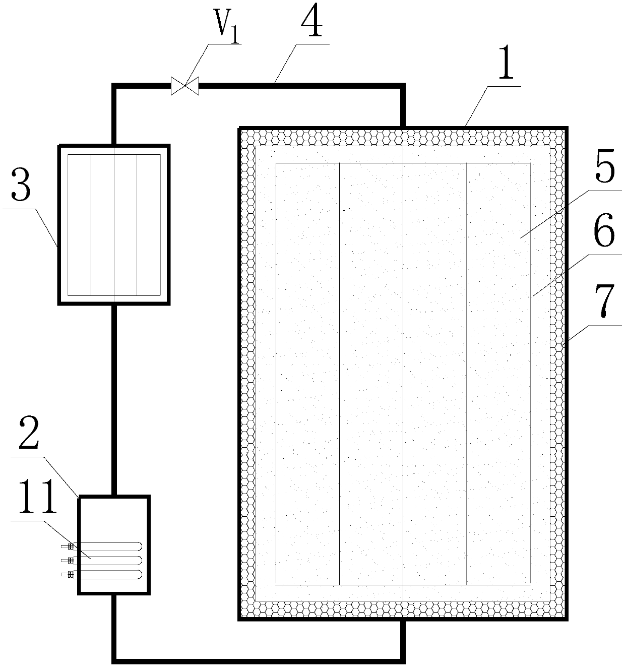
[0036] Such as figure 1 As shown, the energy storage device of the present invention that utilizes the temperature difference self-driven circuit can be applied to waste heat recovery and reuse systems. Heat exchange tube 5, energy storage material 6, insulation layer 7, low temperature fluid 8, high temperature fluid 9 and control valves V1-V4. Wherein, the inner wall of the accumulator 1 is provided with an insulating layer 7, the inner cavity of the accumulator 1 is filled with an energy storage material 6, the heat exchange tube 5 is arranged in the energy storage material 6 in the accumulator 1 along the height direction, and Both the top nozzle and the bottom nozzle of the heat pipe 5 protrude from the accumulator 1, the low heat exchanger 2 and the high heat exchanger 3 are placed outside the accumulator 1, and the high heat exchanger 3 is placed in the low heat exchange above device 2. The heat exchange tube 5, the low-level heat exchanger 2, and the high-level heat ...
Embodiment 2
[0040] Such as figure 2 As shown, the energy storage device of the present invention that utilizes the temperature difference self-driven circuit can be applied to the heat storage heater with valley electricity. The difference between embodiment 2 and embodiment 1 is that the heat source of the low-level heat exchanger 2 is provided by electric heating, the high-level heat exchanger 3 is a heating radiator, the circulating working fluid is R125, and the self-driven heat transfer mode of supercritical fluid is adopted, and other are the same. The heat output can be controlled by controlling the opening of the valve V1. During the valley power time, the electric heater is started, heating and heat supply and heat storage are carried out at the same time, and the valley power heat storage is completed. During non-valley electricity time, the heating and heating rely on the heat storage material in the heat storage to release heat through the high-level heat exchanger 3 to com...
Embodiment 3
[0042] Such as image 3 As shown, the energy storage device of the present invention, which utilizes the temperature difference self-driven circuit, can be applied to the off-peak power heat storage system. The difference from Embodiment 2 is that a heating circulating water system is added. The heating circulating water 8 passes through the circulating water pump 12, absorbs heat in the high-level heat exchanger 3, flows to multiple sets of heating radiators 13, and dissipates heat to the environment.
PUM
 Abstract
Description
Claims
Application Information
 - R&D Engineer
- R&D Manager
- IP Professional
- Industry Leading Data Capabilities
- Powerful AI technology
- Patent DNA Extraction
Browse by: Latest US Patents, China's latest patents, Technical Efficacy Thesaurus, Application Domain, Technology Topic, Popular Technical Reports.
© 2024 PatSnap. All rights reserved.Legal|Privacy policy|Modern Slavery Act Transparency Statement|Sitemap|About US| Contact US: help@patsnap.com