
Slagging backflow transition structure for offshore drill tool

A transitional structure and backflow technology, which is applied in construction and other directions, can solve problems such as differences in absorption capacity, poor torsion resistance, and inconsistent resistance at the absorption port, and achieve the effects of preventing cracking, air leakage, and stress

Inactive Publication Date: 2018-03-27
JIANGSU HUAXICUN OFFSHORE ENG SERVICE +1
View PDF0 Cites 0 Cited by
  • Summary
  • Abstract
  • Description
  • Claims
  • Application Information

AI Technical Summary

Problems solved by technology

[0003] 1. The high-pressure air pipes are all introduced vertically from the top, but due to the limited mechanical structure design, it is impossible to install multi-air independent air pipes, so only one main pipe can be used to introduce high-pressure gas;
[0004] 2. The air duct connected inside the double-wall drill pipe adopts a fixed connection method. Because it is a rigid connection, its torsion resistance is poor. For the drilling tool system for offshore construction, the hydraulic torque is extremely large, so it is easy to drill During the rotation of the rod, the connection between the air pipe and the top and bottom surfaces of the drill pipe breaks, resulting in air leakage and affecting the mixing and discharge of mud and air;
[0005] 3. Conventional drill pipes use one air source and one pipeline. The structure of one pipeline is simple, but the resistance of the corresponding multiple suction ports is inconsistent and the absorption capacity is different. Local blockage is prone to occur, thus affecting the effect of slurry return and slag discharge

Method used


Image

  • Slagging backflow transition structure for offshore drill tool
  • Slagging backflow transition structure for offshore drill tool
  • Slagging backflow transition structure for offshore drill tool

Examples


Embodiment Construction

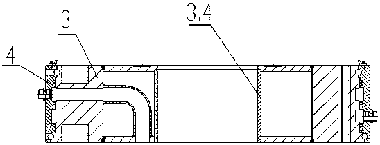
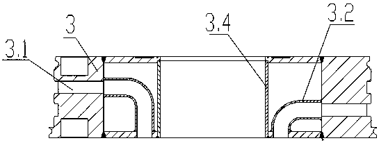
[0031] see Figure 1~10 , the present invention relates to a slagging backflow transition structure for offshore drilling tools, the structure includes a transition joint 6, the transition joint 6 includes an upper small flange 6.2 and a lower large flange 6.3, connecting the cone The upper opening end of 6.1 is fixedly connected to the upper small flange 6.2, and the small opening end is fixedly connected to the lower large flange 6.3, and there are multiple connections between the upper small flange 6.2 and the lower large flange 6.3. Transition air pipe 6.4, the tops of multiple transition air pipes 6.4 correspond to and communicate with multiple in-line air pipes 5.7 in the drill pipe 5 located at the bottom of the drill pipe assembly, and the connecting cone 6.1 is provided with a slag discharge pipe three 6.5, slag discharge branch pipe 1 6.6 and slag discharge connecting taper pipe 6.7, the top of the slag discharge pipe 3 6.5 is connected to the upper small flange 6.2,...


PUM


Abstract

The present invention is a slagging backflow transition structure for offshore drilling tools, which includes a transition joint (6), and the transition joint (6) includes an upper small flange (6.2) and a lower large flange (6.3). There are multiple transition air pipes (6.4) connected between the upper small flange (6.2) and the lower large flange (6.3), and the tops of the multiple transition air pipes (6.4) connect The multiple in-line air pipes (5.7) in the rod (5) correspond to each other and are connected. The connecting cone (6.1) is equipped with a slag discharge pipe three (6.5), a slag discharge branch pipe one (6.6) and a slag discharge connection cone. The pipe (6.7) and the tops of multiple slag discharge branch pipes one (6.6) are connected to the slag discharge pipe three (6.5) through the slag discharge connecting taper pipe (6.7). The invention discloses a slag discharge and return flow transition structure for offshore drilling tools, which has reasonable structure, convenient assembly and good slurry return and slag discharge effect.

Description

technical field [0001] The invention relates to a drilling tool system, in particular to a drilling tool system used in offshore wind power construction drilling technology, and belongs to the technical field of marine construction equipment. Background technique [0002] At present, in the construction of offshore wind power, drilling operation is a very critical link; it needs to carry the drilling slag through the mud and discharge it in time during the downward excavation process, otherwise the drilling slag staying at the bottom of the tunnel will hinder the drilling of the drill bit; In addition, the conventional drilling tool system also has the following disadvantages: [0003] 1. The high-pressure air pipes are all introduced vertically from the top, but due to the limited mechanical structure design, it is impossible to install multi-air independent air pipes, so only one main pipe can be used to introduce high-pressure gas; [0004] 2. The air duct connected insi...

Claims


Application Information

Patent Timeline
Patent Type & Authority Applications(China)
IPC IPC(8): E21B21/16
CPCE21B21/16
Inventor 周宏勤丁明吴建亮张亚东丁志宏钱俊
Owner JIANGSU HUAXICUN OFFSHORE ENG SERVICE
Learn More