Vamp shaping machine with non-rigid shaping plate and double-station carrying table
What is Al technical title?
Al technical title is built by PatSnap Al team. It summarizes the technical point description of the patent document.
A technology of carrying platform and shaping plate, applied in the direction of shoemaking machinery, shoe uppers, footwear, etc., can solve the problems of unfavorable material collection, preparation, safety of pinching, narrow application scope, etc., so as to reduce idle time and avoid potential safety hazards. , the effect of broadening the scope of application
Pending Publication Date: 2018-03-27
鹤山市新易高鞋业有限公司
View PDF5 Cites 0 Cited by
Summary
Abstract
Description
Claims
Application Information
AI Technical Summary
This helps you quickly interpret patents by identifying the three key elements:
Problems solved by technology
Method used
Benefits of technology
Problems solved by technology
However, the existing vamp shaping machine has only a single station, and can only wait for a batch of products to be shaped, and collect and prepare after a batch is shaped, so that the equipment and workers must have a spare time, which cannot be fully utilized. The efficiency is very low; moreover, the carrying platform of the existing vamp shaping machine is generally fixed and cannot be moved. Although its stability is guaranteed, it is not conducive to the work of receiving materials and preparing for work because it is placed under the shaping plate. At the same time, there is also a potential safety hazard of pinching; in addition, the sizing mechanism of the existing vamp sizing machine is a rigid structure, which is difficult to adapt to different thicknesses of the product, and cannot automatically adapt to the adjustment, and it is easy to deform the sizing mechanism due to the transition of force. Or cause damage to the upper, it is difficult to meet the strength requirements of different products, and the scope of application is narrow
Method used
Image
Click on the blue label to locate the original text in one second.
Reading with bidirectional positioning of images and text.
Examples
Embodiment Construction
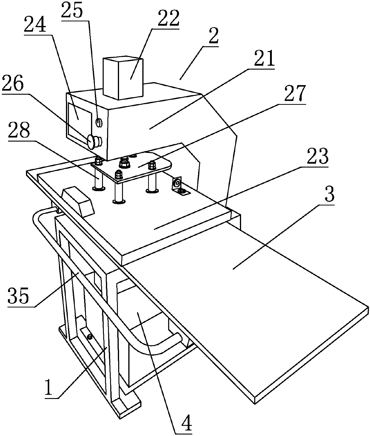
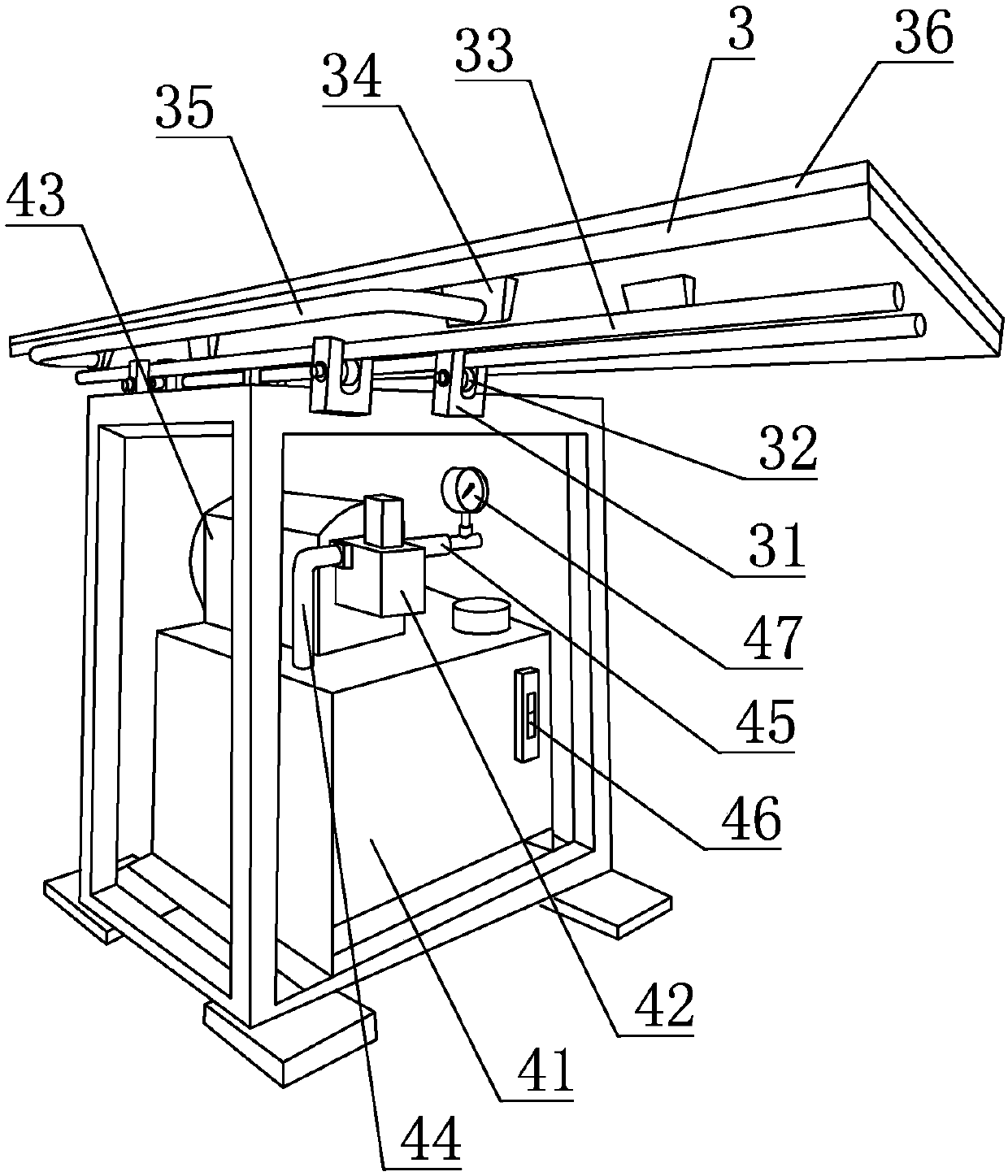
[0015] refer to Figure 1 to Figure 2 ,本发明的一种具有非刚性定型板及双工位承载台的鞋面定型机,包括机架1、安装在机架1上的定型机构2和控制系统,定型机构2下方的机架1上设有承载台3,所述机架1上装有液压站4,所述定型机构2包括固定在机架1上的悬臂21,所述悬臂21上装有定型油缸22,定型油缸22的输出端装有定型板23,所述定型板23内置有加热装置,通过加热装置加热,可使鞋面更快定型,便于加快定型速度;所述液压站4包括固定在机架1上的油箱41和安装在油箱41上的动力油泵42,动力油泵42通过电机43驱动,其吸口通过输入管44探入油箱41内,其出口通过输出管45连接至定型油缸22,所述电机43与控制系统电连接;所述承载台3左右滑动式的设置在机架1顶部,其长度大于或等于定型板23长度的二倍,宽度小于或等于定型板23的宽度;当承载台3可在机架1上左右移动,使其一半始终置于定型板23下方,以便进行鞋面定型处理,而其另一半边则可以进行下一批鞋面产品定型前的准备;当前一批鞋面定型完成后,定型油缸22驱动定型板23上行,随即推动承载台3左右移动,使刚定型完成的部分滑离定型板23下方,并使另一端刚准备好的鞋面滑行至定型板23下方,继续定型,而滑出部分开始收取定型后的鞋面并开始做下一批鞋面定型前的准备,以此类推、循环操作,通过两个工位的设置,可以同时进行鞋面的定型和准备工作,使得定型机持续运行,减少了其闲置时间,极大的提高了生产效率。
PUM
Abstract
The invention discloses a vamp shaping machine with a non-rigid shaping plate and a double-station carrying table. The vamp shaping machine with the non-rigid shaping plate and the double-station carrying table comprises a rack, a shaping mechanism and a control system, wherein the shaping mechanism and the control system are mounted on the rack; the carrying table is arranged on the rack and positioned below the shaping mechanism; a hydraulic station is mounted on the rack; the shaping mechanism comprises a cantilever fixed on the rack; the cantilever is provided with a shaping oil cylinder;a middle plate is mounted at an output end of the shaping oil cylinder; the middle plate is connected with a shaping plate through at least four spring connecting rods; a heating device is placed in the shaping plate; the hydraulic station comprises an oil tank and a power oil pump; the oil tank is fixed on the rack; the power oil pump is mounted on the oil tank; the power oil pump is driven by amotor; a suction opening of the power oil pump extends into the oil tank through an input tube while an outlet of the power oil pump is connected to the shaping oil cylinder through an output tube; the motor is electrically connected with the control system; the carrying table is arranged on the top of the rack in a left-right sliding mode; the length of the carrying table is greater than or equalto two times the length of the shaping plate; and the width of the carrying table is smaller than or equal to that of the shaping plate. By arrangement of the two stations, idle time is shortened, and the production efficiency is improved.
Description
technical field [0001] 本发明涉及制鞋技术领域,尤其涉及一种鞋面定型机。 Background technique [0002] 在制鞋工艺中,鞋面的制作非常重要,鞋面的多层粘合过程中需要进行定型,以便鞋面快速粘合在一起。但是现有的鞋面定型机只有单一工位,在一批产品定型时只能等待,定型好一批后又要收集、准备,导致设备和工人必有一个空闲,不能得到充分的利用,生产效率非常低下;而且现有的鞋面定型机的承载台一般都是固定的,不能移动,虽然保障了其稳定性,但由于置于定型板下方,不利于收料、准备等工作的进行,同时也存在夹伤的安全隐患;此外,现有的鞋面定型机的定型机构为刚性结构,难以很好的适应产品的不同厚度,无法自动适应调节,容易因施力过渡导致定型机构变形,或造成鞋面损伤,难以满足不同产品定型的力度要求,适用范围较窄。因此,有必要对现有的鞋面定型机进行改进和优化。 Contents of the invention [0003] 本发明旨在解决上述所提及的技术问题,提供一种双工位的鞋面定型机,以提高生产效率。 [0004] 本发明是通过以下的技术方案实现的: [0005] 一种具有非刚性定型板及双工位承载台的鞋面定型机,包括机架、安装在机架上的定型机构和控制系统,定型机构下方的机架上设有承载台,所述机架上装有液压站,所述定型机构包括固定在机架上的悬臂,所述悬臂上装有定型油缸,所述定型油缸的输出端装有一中间板,中间板通过至少四条弹簧连接杆连接有定型板,所述定型板内置有加热装置,所述液压站包括固定在机架上的油箱和安装在油箱上的动力油泵,动力油泵通过电机驱动,其吸口通过输入管探入油箱内,其出口通过输出管连接至定型油缸,所述输出管上设有压力传感器,所述压力传感器信号连接至控制系统,所述电机与控制系统电连接;所述承载台左右滑动式的设置在机架顶部,其长度大于或等于定型板长度的二倍,宽度小于或等于定型板的宽度;所述机架顶部两侧各设有至少两个导向叉,每一所述导向叉的叉部装有一个导向轮,所述承载台底侧固定有至少两条导杆,所述导杆置于叉部内的导向轮上。 [0006] 进一步地,所述承载台底侧前部设有两个连接块,两个所述连接块之间设有一平置的U形推杆。 [0007] 进一步地,所述承载台上侧设有与之相同尺寸的缓冲垫。 ...
Claims
Application Information
Patent Timeline
Application Date:The date an application was filed.
Publication Date:The date a patent or application was officially published.
First Publication Date:The earliest publication date of a patent with the same application number.
Issue Date:Publication date of the patent grant document.
PCT Entry Date:The Entry date of PCT National Phase.
Estimated Expiry Date:The statutory expiry date of a patent right according to the Patent Law, and it is the longest term of protection that the patent right can achieve without the termination of the patent right due to other reasons(Term extension factor has been taken into account ).
Invalid Date:Actual expiry date is based on effective date or publication date of legal transaction data of invalid patent.