Inverse design method for electroosmosis microfluid electrode layout

A design method and microfluidic technology, applied in computing, electrical digital data processing, special data processing applications, etc., can solve problems such as low design efficiency, lack of universality, flexibility, and electrode layout design limitations

Inactive Publication Date: 2018-03-23
CHANGCHUN INST OF OPTICS FINE MECHANICS & PHYSICS CHINESE ACAD OF SCI
View PDF3 Cites 4 Cited by
  • Summary
  • Abstract
  • Description
  • Claims
  • Application Information

AI Technical Summary

Problems solved by technology

Although some related studies provide guidance for electroosmotic control, these studies mainly rely on the designer's intu

Method used


Image

  • Inverse design method for electroosmosis microfluid electrode layout
  • Inverse design method for electroosmosis microfluid electrode layout
  • Inverse design method for electroosmosis microfluid electrode layout

Examples


Embodiment Construction

[0061] The present invention will be described in more detail below in conjunction with the drawings and embodiments.

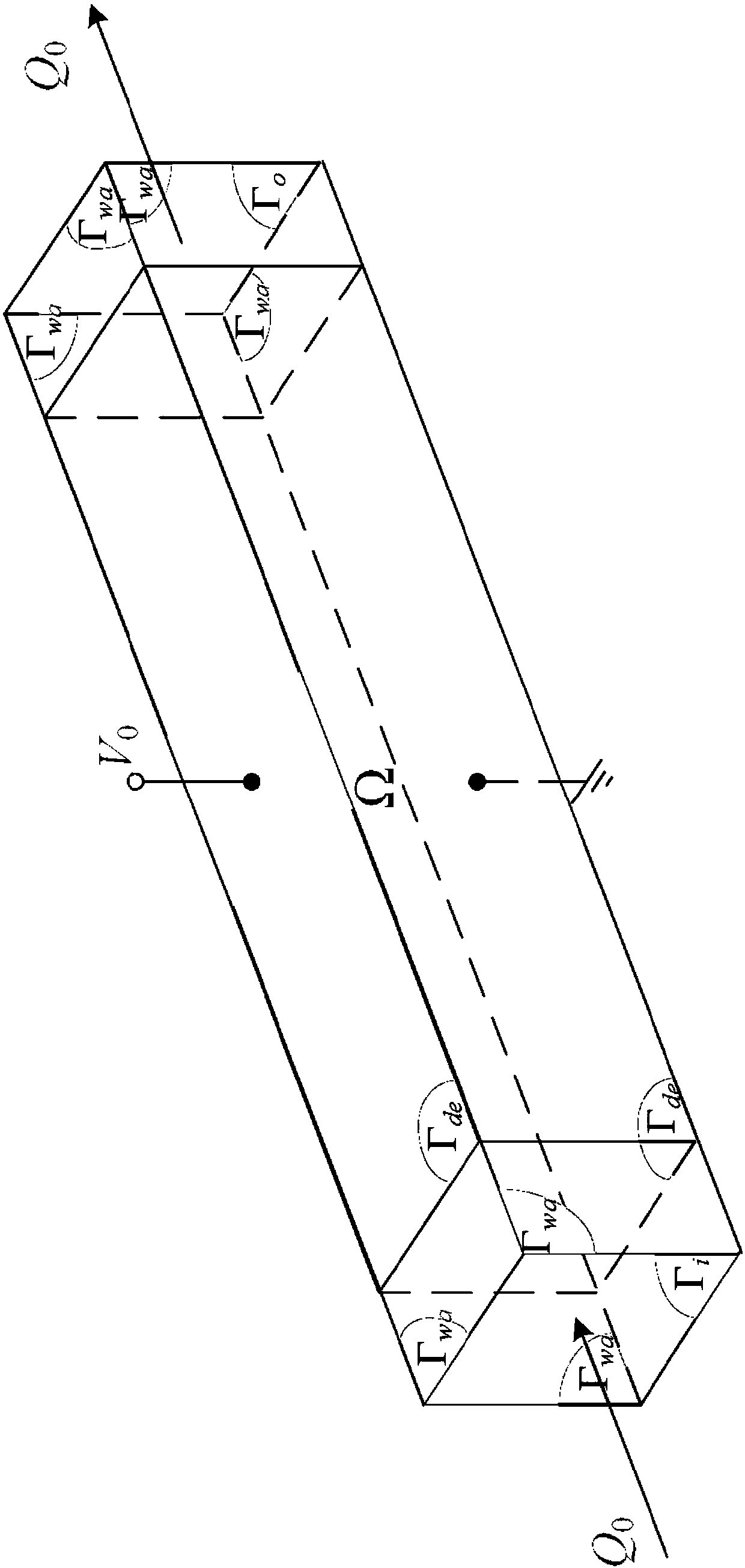
[0062] The invention discloses an inverse design method of electroosmotic microfluid electrode layout, please refer to figure 1 , Which includes the following steps:

[0063] Step S1, under the assumption of continuum, use Navier-Stokes equation to describe microfluid motion:

[0064]

[0065] In the formula, u is the fluid velocity, p is the fluid pressure, ρ is the density of the electrolyte solution, η is the dynamic viscosity of the electrolyte solution, Ω is the calculation area, and the inlet boundary is Γ i , The sidewall boundary is Γ w , The exit boundary is Γ o , And meet

[0066] Step S2, under the assumption that the thickness of the Debye layer is much smaller than the characteristic scale of the microfluid, according to the Helmholtz-Smoluchowski theory applied to the inner wall of the electroosmotic microchannel, it is concluded that the slip velocity...


PUM


Abstract

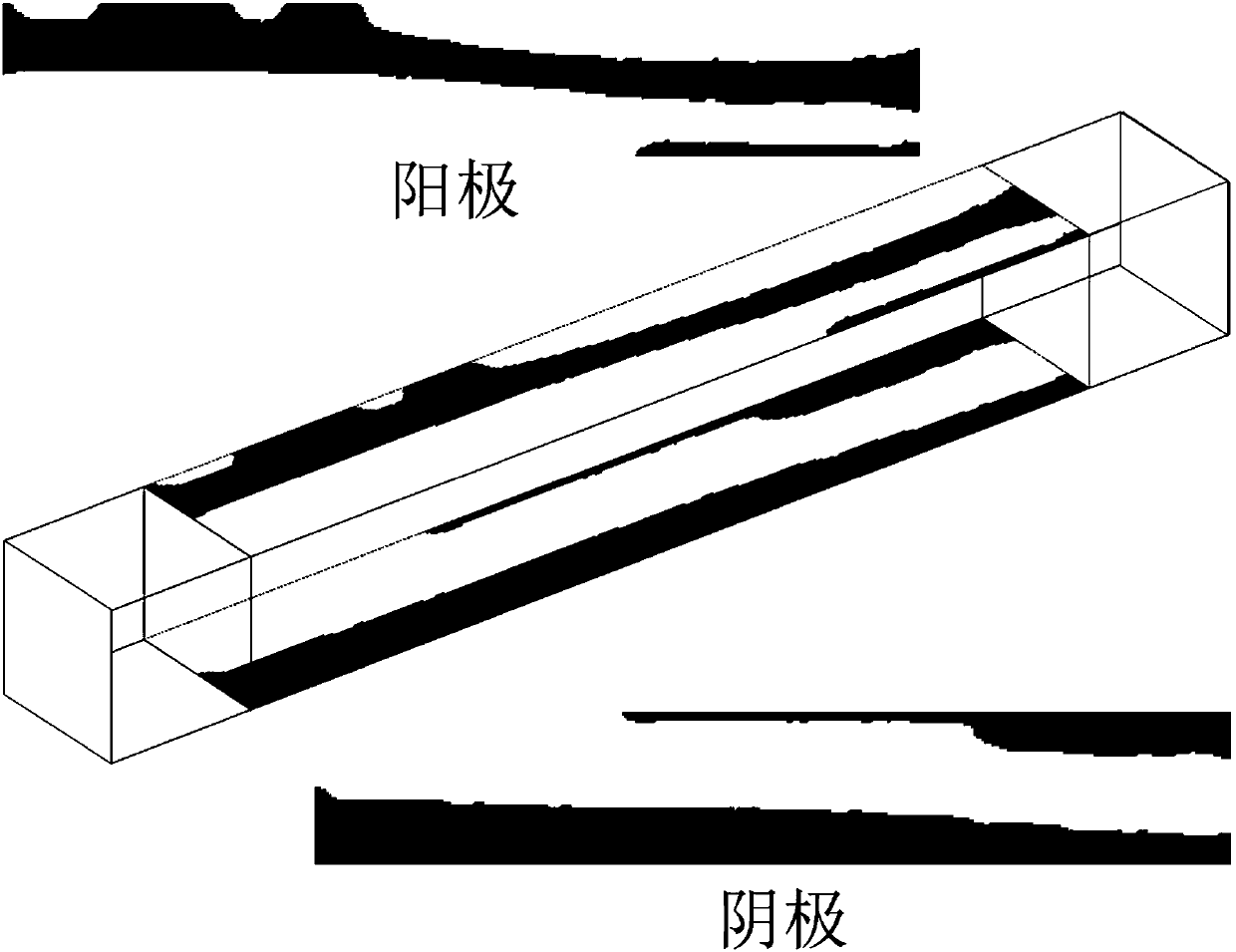
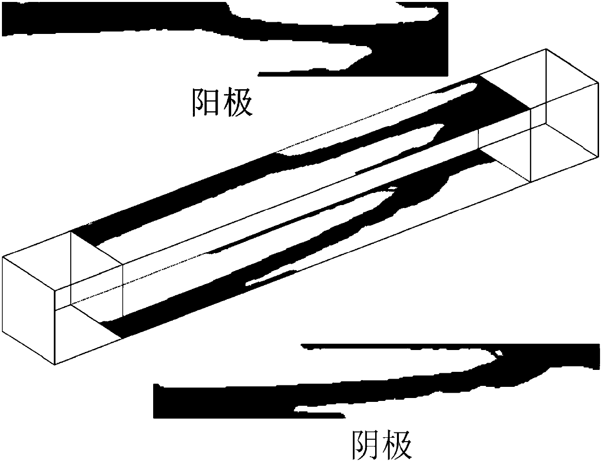
The invention discloses an inverse design method for an electroosmosis microfluid electrode layout. The method comprises the following steps: step S1, in continuous medium hypothesis, using a Navier-Stokes equation to describe microfluid movement; step S2, based on that a Helmholtz-Smoluchowski theory is suitable for an electroosmosis microchannel inner wall, obtaining that slip velocity being indirect proportion to a tangential component of electric field intensity caused by an electrode; step S3, introducing a defected boundary condition on an entrance of the electroosmosis microfluid; stepS4, a side wall boundary [tau]w being divided into two parts, [tau]wa and [tau]de, a boundary condition of the[tau]de being interpolation of electric insulation and potential; step S5, using Helmholtz to filter a design variable, to control a feature size of a layout; step S6, using a threshold method to project the filtered design variable, eliminating values between 0 and 1, and deriving a physical density variable; step S7, through solving a variational problem, obtaining 0-1 distribution of physical density, to obtain an electrode layout on the boundary [tau]de. The method overcomes limitation on existing electrode design, and has universality and flexibility.

Description

Technical field [0001] The invention relates to an electrode layout design method for the inner wall of an electroosmotic microchannel on a microfluidic chip used in biochemical detection, in particular to an inverse design method for an electroosmotic microfluidic electrode layout. Background technique [0002] Lab-on-a-chip is widely used in rapid testing in the fields of biology and chemistry. When using microfluidic chips for biochemical testing, it is usually necessary to use pumps to drive and control fluid movement, enhance mixing effects, and separate fluids. Electroosmosis technology is especially suitable for the field of microfluidics because it meets the requirement of no moving parts on micro devices. At present, there are a large number of literatures on electroosmosis technology, which mainly includes the research of electroosmosis micromixer. Electroosmosis is caused by the induced charges on the solid surface contacted by the electrolyte solution. The charge i...

Claims


Application Information

Patent Timeline
IPC IPC(8): G06F17/50
CPCG06F30/00
Inventor 邓永波纪元吴一辉刘洵刘永顺刘震宇
Owner CHANGCHUN INST OF OPTICS FINE MECHANICS & PHYSICS CHINESE ACAD OF SCI
Why Eureka
Try Eureka