


Quick Research
Generate reliable direction feasibility study reports for your R&D in just a few steps.

Technical Q&A
Discover and master advanced knowledge NOW. Basics, ideas, possibilities, all at once.

Find Solutions
As an expert in R&D theories, this can generate solutions to your technical problems instantly.

Evaluate Feasibility
Analyze your overall solution with one click, know your potential R&D risks in advance.

Monitor Landscape
Get weekly tech updates, stay abreast of the latest tech innovations and key insights.
Thin-wall rotary type component cylindrical lathe cutting clamping method and device
A thin-walled rotary and parts technology, which is applied in the field of clamping methods and devices for external turning of thin-walled rotary parts, can solve the problems of difficulty in controlling clamping force, inability to press-fit the end face, and inappropriate clamping methods. The clamping force is uniform, the irregular deformation is avoided, and the clamping method is reliable.
- Summary
- Abstract
- Description
- Claims
- Application Information
AI Technical Summary
Problems solved by technology
Method used
Image

Examples
Embodiment 1
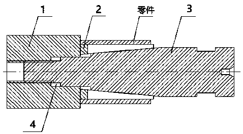
[0018] Example 1. A clamping method for external turning of thin-walled rotary parts, such as Figure 1 to Figure 3 As shown, this method achieves the purpose of clamping thin-walled rotary parts by tightening the inner hole of thin-walled rotary parts.
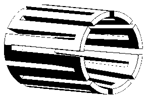
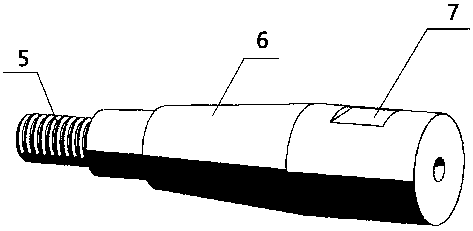
[0019] The method is to set the threaded cone ejector rod and the elastic hollow shaft, and use the relative movement of the threaded cone ejector rod and the elastic hollow shaft to expand the elastic hollow shaft and tighten the inner hole of the thin-walled rotary parts, so as to realize the thin-walled rotary parts. The purpose of clamping the wall rotary parts is to avoid the irregular deformation of the thin wall rotary parts; the elastic hollow shaft is moved by the threaded cone ejector rod, so that the inner cone surface of the elastic hollow shaft is on the top of the threaded cone surface. The outer tapered surface of the rod moves, so that the elastic hollow shaft expands and tightens the inner hole of the thin-w...
Embodiment 2
[0023] Example 2. like Figure 1-4 as shown, Figure 4 The parts are steel parts with a total length of 47.2mm, an outer diameter of 9.8mm, an inner hole diameter of 8.9mm, and a wall thickness of less than 0.45mm. The inner hole tolerance requirements are strict, and the tolerance zone is 0.015mm. Very difficult.
[0024] Tooling installation processing steps:
[0025] 1. Tooling preparation:
[0026] Base, elastic hollow shaft, threaded taper ejector rod and machine tailstock;
[0027] 2. Tooling installation
[0028] Connect the base 1 with the spindle of the CNC lathe through a chuck, and align the guide hole 4 to be concentric with the spindle of the machine tool.
[0029] Put the elastic hollow shaft 2 on the threaded conical ejector rod 3, then insert the threaded tapered ejector rod 3 into the guide hole 4 of the base 1, and screw it into the thread, so as to ensure that the elastic hollow shaft 2 can be placed on the threaded conical top. Move on bar 3.
[003...
PUM
 Abstract
Description
Claims
Application Information
 - R&D Engineer
- R&D Manager
- IP Professional
- Industry Leading Data Capabilities
- Powerful AI technology
- Patent DNA Extraction
Browse by: Latest US Patents, China's latest patents, Technical Efficacy Thesaurus, Application Domain, Technology Topic, Popular Technical Reports.
© 2024 PatSnap. All rights reserved.Legal|Privacy policy|Modern Slavery Act Transparency Statement|Sitemap|About US| Contact US: help@patsnap.com