
Throttling type gas-liquid exchange device

A gas-liquid exchange and throttling technology, used in separation devices, using liquid separation agents, cleaning hollow objects, etc., can solve problems such as unsolved equipment water consumption, waste of water resources, and water cannot flow naturally from the overflow port.

Pending Publication Date: 2018-03-23
卓卫民
View PDF5 Cites 0 Cited by
  • Summary
  • Abstract
  • Description
  • Claims
  • Application Information

AI Technical Summary

Problems solved by technology

However, most wet dust removal systems have the following problems: 1. Under the action of the induced draft fan, the wet dust removal equipment is in a negative pressure state inside the equipment. Under the action of atmospheric pressure, the water inside the equipment cannot be removed from The overflow port flows out naturally, and the particulate dust cannot be carried out with the overflow water. The water in the equipment cannot overflow normally, and the water volume is unstable, which will also cause unstable operation of the equipment.
2. The water consumption of general wet dedusting equipment is large, which wastes water resources and increases the load of sewage treatment system at the same time
However, this device does not solve the problem that when the equipment is under negative pressure under the action of the induced draft fan at the air outlet, the water in the equipment cannot overflow normally, and the equipment cannot operate stably.
When those skilled in the art need to adjust the water level at the overflow port, it is easy to think of using the overflow regulating plate to adjust the water level. When the pressure on both sides of the overflow port is different, such as one side is normal pressure and one side is negative pressure, A simple overflow regulating plate cannot meet the requirements of adjusting the water level. Under the action of the pressure difference, the corresponding position of the regulating plate will correspond to the height of multiple water levels. The two sides of the orifice cannot meet the water level requirements of the gas-liquid exchange device
The device also does not address the issue of equipment water consumption

Method used


Image

  • Throttling type gas-liquid exchange device
  • Throttling type gas-liquid exchange device
  • Throttling type gas-liquid exchange device

Examples


Embodiment 1

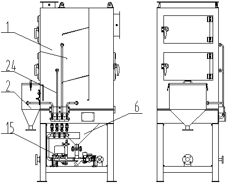
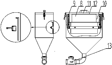
[0032] like figure 1 As shown, the throttling type gas-liquid exchange device of the present invention comprises: main box body 1, negative pressure water tank 2, inlet and outlet 3, as Figure 5 The shown main box 1 has an air inlet 4, an air outlet 5, a throttle plate 7, an overflow port 8, and a water baffle 14. An induced draft fan is arranged at the air outlet 5, and the throttle plate 7 is vertical Fixed in the main box body 1, the main box body 1 is divided into two parts: the air inlet chamber and the air outlet chamber, the air inlet port 4 is located in the air inlet chamber, the air outlet port 5 is located in the air outlet chamber, and the inlet and outlet ports 3 are located in the main box body The bottom of 1 is used to supply water or drain water to the main box 1. The water baffles 14 are distributed on the throttling plate 7 and the wall of the main box 1 in sequence, parallel to the horizontal plane, and the distance between them is equal. The overflow por...

Embodiment 2

[0036] like Image 6 As shown, the throttling gas-liquid exchange device chamber provided in this embodiment is based on the first embodiment, and a settling bucket 6 is arranged under the main box body 1 , and an inlet and outlet 3 are arranged at the bottom of the settling bucket 6 .

[0037] The repose angle α of the settling bucket 6 can make the ash in the settling bucket 6 settle to the bottom of the box bucket. The angle of the angle of repose α of the descending bucket 6 is 45°. Setting the settling bucket 6 can make the dust entering the water enter the bottom of the settling bucket 6, and can realize fast replenishment and discharge of water.

Embodiment 3

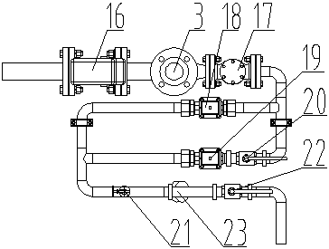
[0039] like image 3 As shown, the throttling type gas-liquid exchange device chamber provided in this embodiment is based on the second embodiment, and an inlet and drain component 15 is added to the throttle type gas-liquid exchange device. Connection, the inlet and outlet parts 15 include the drain electric ball valve 16, the check valve 17, the water inlet solenoid valve 18, the water replenishment solenoid valve 19, the water replenishment control manual ball valve 20, the water hammer buffer 21, the total water inlet control manual ball valve 22, the filter 23. The water replenishment solenoid valve 19 and the water replenishment control manual ball valve 20 are connected in series, and the water inlet solenoid valve 18 and the water replenishment solenoid valve 19 and the water replenishment control manual ball valve 20 connected in series are respectively connected in two branches to form a parallel connection, and one end of the branch is connected in parallel. It is ...


PUM

PropertyMeasurementUnit
Angleaaaaaaaaaa
Angleaaaaaaaaaa
Angleaaaaaaaaaa

Abstract

The invention relates to a throttling type gas-liquid exchange device. The throttling type gas-liquid exchange device comprises a main box, a water feeding and draining opening, a negative-pressure water tank and the like. By effects of the negative-pressure water tank, the air pressure of the inside of the main box is the same as that of the inside of the negative-pressure water tank, the negative-pressure water tank does not communicate with the atmosphere, thus, the water level in the main box is stable, and it can be ensured that the throttling type gas-liquid exchange device is not affected by atmospheric pressure during running, and can run stably. Meanwhile, the device is further provided with a water feeding and draining component and a spraying and cleaning system; the use amountof equipment is small; deposited dust can be prevented from corroding the equipment; and the whole equipment is advanced.

Description

technical field [0001] The invention relates to a gas-liquid exchange device, belonging to the technical field of gas-liquid exchange. Background technique [0002] Wet dedusting equipment generally uses water as the purification medium. The particulate pollutants in the waste gas can be effectively removed through the same equipment to capture the particulate pollutants. The removal efficiency is high. The treatment process generally produces a certain amount of sewage, but as the sewage With the development of treatment technology, the sewage generated by wet dedusting equipment can be effectively resolved, and the weight of advantages and disadvantages of wet dedusting equipment has changed. Wet dedusting systems are generally more compact than dry dedusting systems, occupy less land, and have lower initial investment. High efficiency, can be processed nearby. However, most wet dust removal systems have the following problems: 1. Under the action of the induced draft fan...

Claims


Application Information

Patent Timeline
IPC IPC(8): B01D47/02B08B9/093
CPCB01D47/02B08B9/093B01D2247/06
Inventor 卓卫民
Owner 卓卫民
Learn More