
Telephone receiver

A receiver and cavity technology, applied in the field of receivers, can solve problems such as poor low frequency characteristics of receivers, and achieve the effects of simple assembly process, improved sound, and reduced height

Pending Publication Date: 2018-03-20
SUZHOU YICHUAN TECH CO LTD
View PDF10 Cites 16 Cited by
  • Summary
  • Abstract
  • Description
  • Claims
  • Application Information

AI Technical Summary

Problems solved by technology

[0005] Therefore, the technical problem to be solved by the present invention is that the low-frequency characteristics of existing receivers are poor

Method used


Image

  • Telephone receiver
  • Telephone receiver
  • Telephone receiver

Examples


Embodiment 1

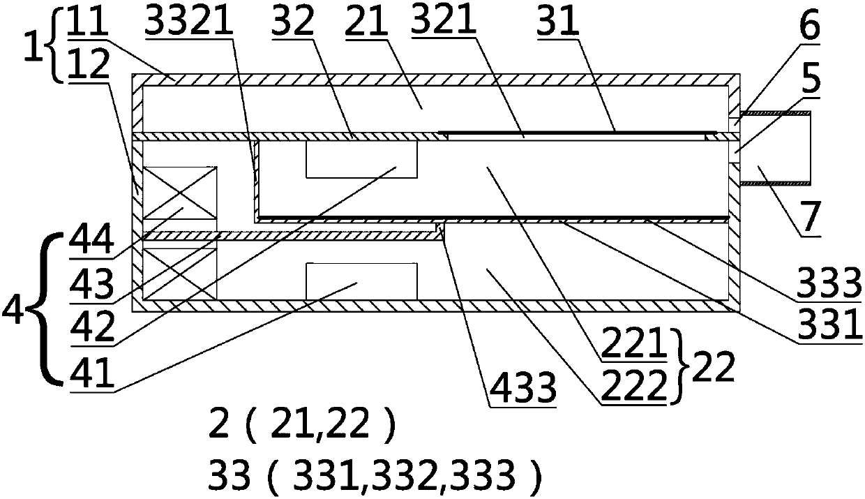
[0052] This embodiment provides a receiver, such as figure 1 As shown, it includes a housing 1 , a diaphragm mechanism, a driving mechanism 4 , a first sound outlet 5 and a second sound outlet 6 . Wherein, the diaphragm mechanism includes a main vibration assembly 33 , a first sound diaphragm 31 and an isolation component 32 .

[0053] The shell 1 has a hollow cavity 2; the first sounding membrane 31 is fixed on the inner wall of the shell 1, and the hollow cavity 2 is divided into a first cavity 21 and a second cavity 22 which are not connected, preferably an elastic film The main vibrating assembly 33 is installed in the second inner cavity, and the second inner cavity is divided into a main sound cavity 221 and an installation cavity 222 that are side by side with the first cavity 21 and are not connected, and the main sound cavity 221 is close to the first cavity. One side of the sounding membrane 31; correspondingly, the cavity 222 is installed away from the side of the ...

Embodiment 2

[0074] This embodiment provides a receiver. Compared with the structure of the receiver provided in Embodiment 1, the only difference is that the first sound-sounding film 31 has two layers, three layers, four layers or more layers, and the adjacent The first acoustic membranes 31 are arranged parallel to each other and separated by a required distance.

[0075] Each first sounding film 31 is installed on the housing 1 by a spacer 32, the spacer 32 offers a first through hole 321, the first sound film 31 is sealed and installed on the first through hole 321, the edge of the spacer 32 The seal is installed on the inner wall surface of the first housing 11 , the outer end surface of the opening of the first housing 11 , or the outer end surface of the opening of the second housing 12 .

[0076] The innermost first sounding membrane 31, the isolation member 32, the main vibration assembly 33 and the inner wall of part of the second housing 12 enclose the main sound cavity 221; th...

Embodiment 3

[0079] This embodiment provides a receiver. Compared with the structure of the receiver provided in Embodiment 1 or 2, the only difference is that the shell 1 can be composed of a first shell 11, a second shell 12, and a third shell. A plurality of shells are formed together, and both ends of the shell in the middle are provided with openings, and the specific number is determined by the needs of production and processing.


PUM


Abstract

The invention discloses a telephone receiver. The telephone receiver comprises a shell with a hollow cavity; a first sound producing membrane arranged on the shell and used for diving the hollow cavity into a first cavity and a second cavity; a main vibration component arranged in the second cavity and used for dividing the second cavity into a main sound producing cavity and a mounting cavity, wherein a first sound hole and a second sound hole are respectively formed on the shell to correspond to the wall surface of each of the main sound producing cavity and the first cavity; and a driving mechanism arranged in the second cavity; the driving mechanism drives the main vibration component to vibrate, the vibration drives the first sound producing membrane to vibrate through the air in themain sound producing cavity; the sound produced by each of the main vibration component and the first sound vibrating membrane is converged; the vibration of the first sound producing membrane maintains a certain lagging in comparison with the main vibration component, so that the sound produced by the first sound producing membrane and the sound produced by the main vibration component can produce the reverberation effect, thereby perfecting the low-frequency feature of the telephone receiver, and improving the fullness and depth of the sound.

Description

technical field [0001] The invention belongs to the technical field of electroacoustic conversion, and in particular relates to a receiver. Background technique [0002] Receiver, also called earpiece, is an electroacoustic device that converts audio electrical signals into sound signals without sound leakage. It is widely used in communication terminal equipment such as mobile phones, fixed phones, and hearing aids to realize audio (voice, music) replay. The main principle of the receiver is to use electromagnetic induction and piezoelectric effect, and there are also capacitive earphones that use the principle of capacitors, and receivers that use the principle of electromagnetic induction mainly include moving iron receivers and moving coil receivers. Most of the existing moving iron receiver structures are disclosed in Chinese patent document CN103747374A as a receiver with an improved casing, which includes a casing, a diaphragm, and an electromagnetic drive mechanism....

Claims


Application Information

Patent Timeline
Patent Type & Authority Applications(China)
IPC IPC(8): H04R9/06H04R9/02
CPCH04R9/02H04R9/06H04R2400/11H04R11/02H04R17/00H04R1/2834H04R1/2842
Inventor 陈晓明吴哲
Owner SUZHOU YICHUAN TECH CO LTD
Learn More