
Battery management system with potential fault analysis and diagnosis function

A battery management system and fault analysis technology, which is applied to secondary batteries, secondary battery repair/maintenance, circuits, etc., can solve problems such as shortened service life, battery pack performance degradation, and slow judgment process of fuzzy systems, so as to improve the use of Efficiency, ease of connection to the effect

Inactive Publication Date: 2018-03-20
安徽特凯新能源科技有限公司
View PDF0 Cites 8 Cited by
  • Summary
  • Abstract
  • Description
  • Claims
  • Application Information

AI Technical Summary

Problems solved by technology

However, due to the slow judgment process of the fuzzy system and the need for a large amount of experimental data to form an expert system;
[0004] (2) Existing fault management systems lack a battery balancing system
[0005] (3) The battery pack, especially the power battery for electric vehicles, is composed of dozens or hundreds of single cells connected in series to provide energy for the battery car. Due to the individual differences between the single cells, and the operation may be caused by Different states lead to inconsistent performance of single batteries, that is, some batteries become backward batteries and some batteries are in better condition.
In this case, the performance of these backward single cells or module batteries determines the performance of the entire battery pack, that is, the performance of the entire battery pack is also reduced, and because the backward battery and the healthy battery are used in series, the service life is further shortened

Method used


Image

  • Battery management system with potential fault analysis and diagnosis function
  • Battery management system with potential fault analysis and diagnosis function
  • Battery management system with potential fault analysis and diagnosis function

Examples


Embodiment

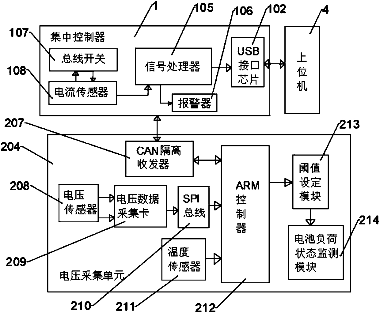
[0034] Such as figure 1 As shown, the present invention provides a battery management system with a potential fault analysis and diagnosis function, including a centralized controller 1, a battery management system 2 and a battery pack monitoring module 3, the positive and negative ports of the centralized controller 1 are respectively The positive main relay 100 and the negative main relay 101 are connected to the battery management system 2, the control terminal of the battery management system 2 is connected to the battery pack monitoring module 3, and the centralized controller 1 is provided with a current sensor 104 inside, The signal end of the current sensor 104 is connected to the battery pack monitoring module 3 through the SCI communication interface 103, the control end of the battery pack monitoring module 3 is connected to the battery management system 2, and the centralized controller 1 monitors the energy storage in real time. The status of all single batteries ...


PUM


Abstract

The invention discloses a battery management system with a potential fault analysis and diagnosis function. The battery management system comprises a centralized controller and a battery management system body, wherein positive and negative electrode ports of the centralized controller are connected with the battery management system body through a positive electrode main relay and a negative electrode main relay respectively; a control end of the battery management system body is connected with a battery pack monitoring module; a signal end of a current sensor is connected with the battery pack monitoring module through an SCI (Serial Communication Interface); the control end of the battery pack monitoring module is connected with the battery management system body; the battery managementsystem body is internally provided with a main controller; the signal end of the main controller is connected with a voltage acquisition unit; a communication port of the main controller is further connected with a CAN (Controller Area Network) bus interface; the whole system is used for carrying out safety monitoring and effective management on a battery pack and improving the utilization efficiency of a battery; the aims of increasing a continuous driving mileage, prolonging the service life and reducing the operation cost are realized.

Description

technical field [0001] The invention relates to the technical field of battery management systems, in particular to a battery management system with potential fault analysis and diagnosis functions. Background technique [0002] The modern electric vehicle is a brand new machine, it is completely different from the traditional electric vehicle, it is not only a transport vehicle, but also a brand new electrical device. Modern electric vehicles consist of electric motors, power converters and batteries as their core components, and the characteristics of the power part are fundamentally different from those of internal combustion engines. Modern electric vehicle science is an emerging interdisciplinary subject for the study of modern electric vehicles. Its core is how to use electric energy to drive vehicles most effectively and environmentally friendly, and realize system integration and optimization. Power batteries are used as energy components of electric vehicles. Unsat...

Claims


Application Information

Patent Timeline
Patent Type & Authority Applications(China)
IPC IPC(8): H01M10/42G01R31/36
CPCG01R31/3646G01R31/371G01R31/382H01M10/4207H01M10/425H01M2010/4271H01M2010/4278Y02E60/10
Inventor 许秀荣陈庆捷许雅莉罗俊俏
Owner 安徽特凯新能源科技有限公司
Learn More