
Fuel high-pressure pump

A high-pressure pump and fuel technology, which is applied in the direction of fuel injection pump, fuel injection device, charging system, etc., to achieve the effect of low-cost manufacturing and material saving

Inactive Publication Date: 2018-03-20
ROBERT BOSCH GMBH
View PDF17 Cites 0 Cited by
  • Summary
  • Abstract
  • Description
  • Claims
  • Application Information

AI Technical Summary

Problems solved by technology

[0003] The problem of the invention is solved by the fuel high pressure pump according to the invention

Method used


Image

  • Fuel high-pressure pump
  • Fuel high-pressure pump
  • Fuel high-pressure pump

Examples


Embodiment Construction

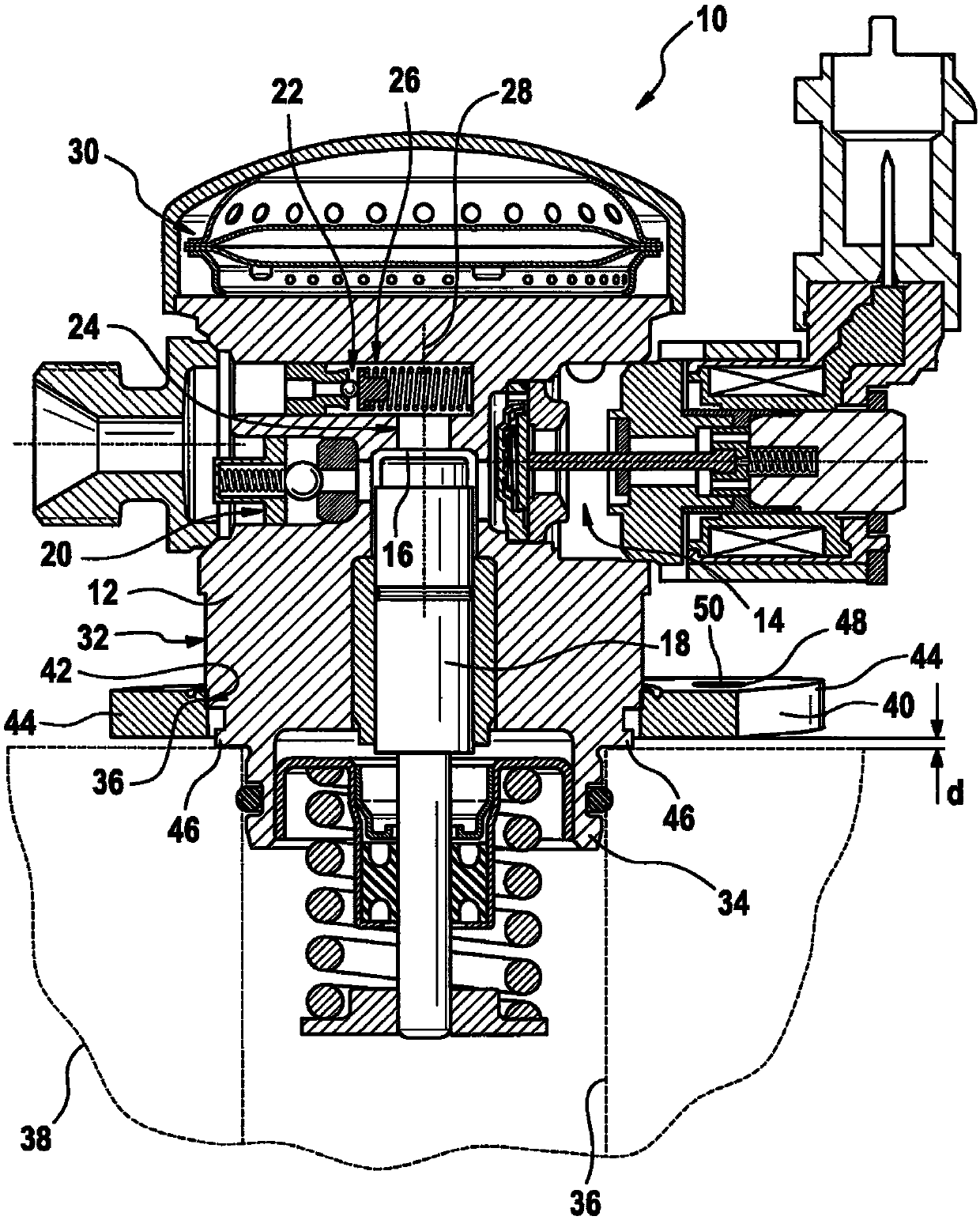
[0024] exist figure 1 The high-pressure fuel pump for an internal combustion engine, not shown in any further detail, bears the reference numeral 10 as a whole. The high-pressure fuel pump 10 has an overall substantially cylindrical pump housing 12 in or on which the essential components of the high-pressure fuel pump 10 are arranged. The high-pressure fuel pump 10 has an inlet / quantity control valve 14 ; a delivery piston 18 arranged in a delivery chamber 16 , which can be set in reciprocating motion via a drive shaft (not shown); an outlet valve 20 ; and a pressure limiting valve 22 .

[0025] In the housing 12 there is a first channel 24 which extends coaxially to the delivery chamber 16 and to the delivery piston 18 and leads from the delivery chamber 16 to a second channel 26 which is opposite to the Arranged at an angle of 90° to the first channel 24 and the pressure limiting valve 22 is received in this second channel. The longitudinal axis of the pump housing 12 is a...


PUM


Abstract

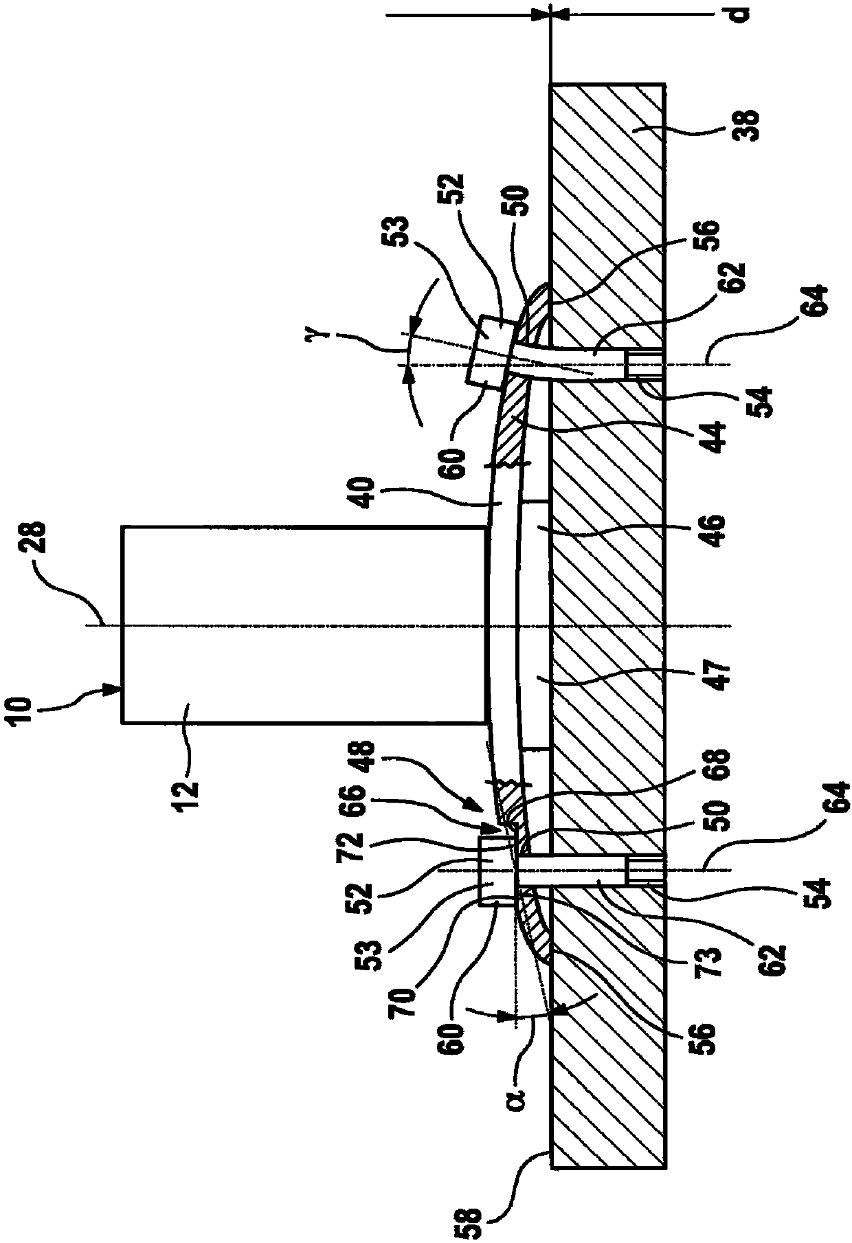
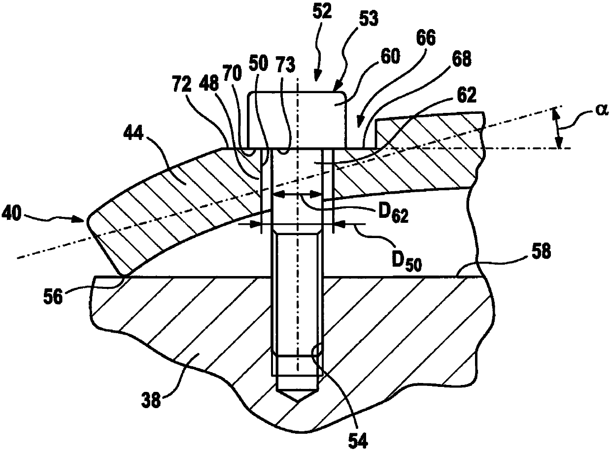
The invention relates to a fuel high-pressure pump (10) with a fixing flange (40) which can be fixed on a holding body (38) in an installed state by means of a fastening means (52), wherein the fuel high-pressure pump (10) has a spacer section (47), which causes a distance between the holding body and a fixing section (48) of the fixing flange (40) in the installation state.

Description

technical field [0001] The invention relates to a high-pressure fuel pump for a fuel injection system of an internal combustion engine. Background technique [0002] Such high-pressure fuel pumps generally comprise a pump housing with a fastening flange fastened thereto. The fastening flange has a fastening section on which a fastening element for fastening acts on the holding body in the mounted state. Due to the construction, the connection between the flange and the housing is subjected to strong mechanical loads due to pressure, vibrations and especially when the clamping elements are screws, due to clamping forces. The holding body can be, for example, a camshaft housing, a cylinder head or another housing. The fastening element can, as shown, be a screw in particular. Here, the screw connection must ensure a tight fit of the pump and thus a durable and reliable function of the pump. Here, overloading or even failure of the screw connection must be avoided. Since a...

Claims


Application Information

Patent Timeline
IPC IPC(8): F02M59/44F16B35/04F16B43/02
CPCF02M59/44F16B35/041F16B43/02F02M59/48F16B5/02F16B31/04
Inventor K·朗
Owner ROBERT BOSCH GMBH
Learn More