
Sewage treatment system for dye printing

A sewage treatment system and sludge treatment technology, applied in water/sewage treatment, biological water/sewage treatment, flotation water/sewage treatment, etc., can solve the complex composition of printing and dyeing wastewater, reduce the content of trace elements in water body, and a single treatment method Unable to achieve the ideal treatment effect, etc.

Pending Publication Date: 2018-03-20
嘉兴市泰石漂染有限公司
View PDF2 Cites 4 Cited by
  • Summary
  • Abstract
  • Description
  • Claims
  • Application Information

AI Technical Summary

Problems solved by technology

There are mainly four treatment methods for printing and dyeing wastewater, physical treatment, chemical treatment, biological treatment, and alkali reduction treatment. However, due to the complex composition of printing and dyeing wastewater, a single treatment method often cannot achieve the desired treatment effect. For example, the application number is The patent title disclosed in 201520398981.X is a kind of anaerobic and aerobic integrated device in a printing and dyeing wastewater treatment device. On the one hand, it can save equipment and reduce cost investment. It can be used in the anaerobic stage and further reduces the trace element content of the water body. Through the electrolytic cell equipped with activated carbon and metal filters, the organic pollutants, pigments and some inorganic salts in the printing and dyeing wastewater are completely removed, and the water quality is effectively improved. However, for textile printing and dyeing wastewater that is difficult to biochemically treat, the anaerobic reaction can only treat part of the organic matter, and a large part of the refractory organic matter cannot be completely decomposed.

Method used

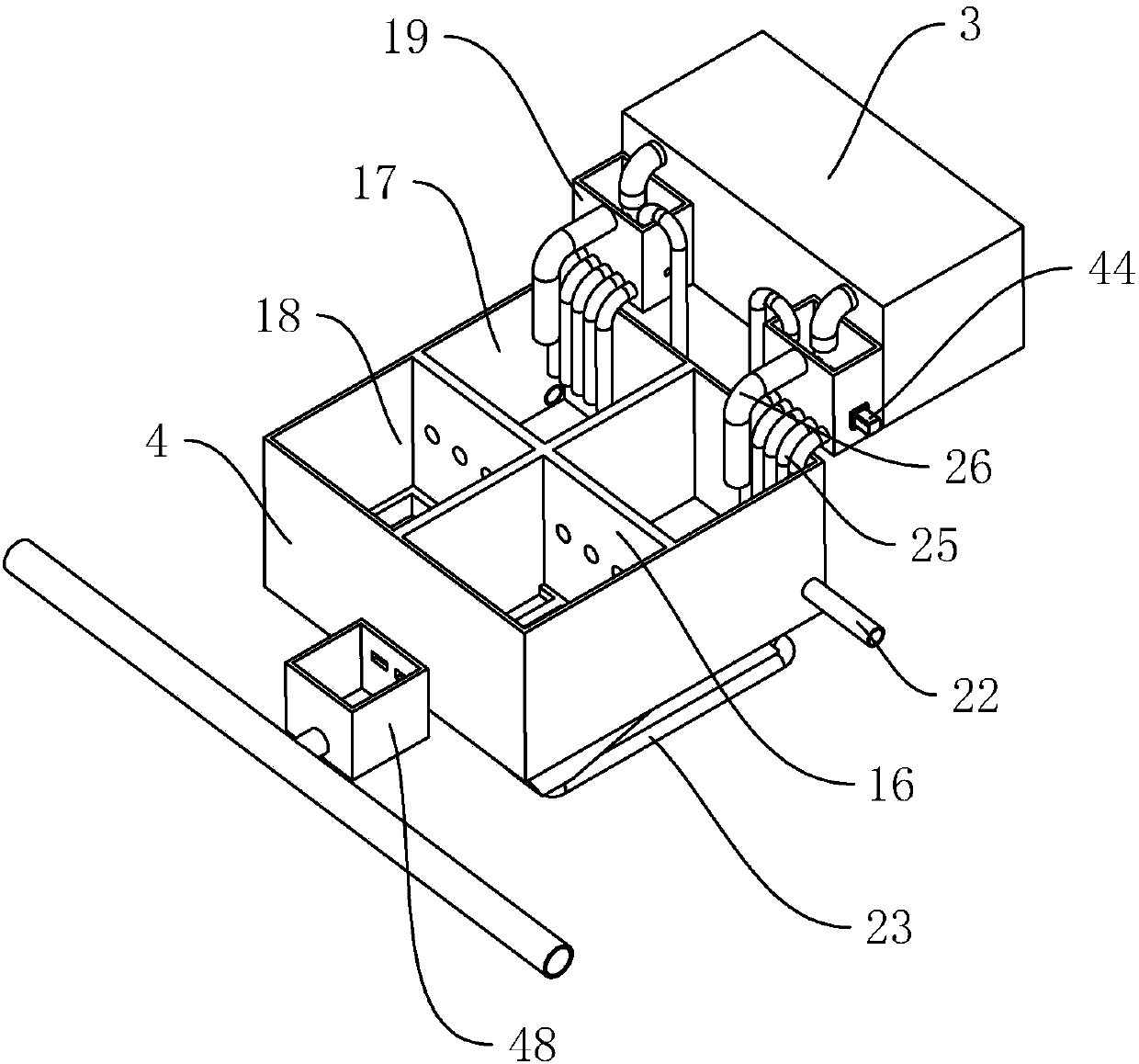
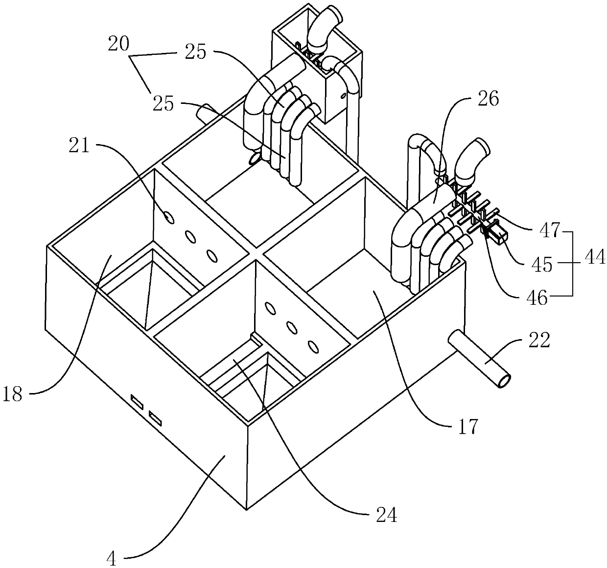

Image

  • Sewage treatment system for dye printing
  • Sewage treatment system for dye printing
  • Sewage treatment system for dye printing

Examples


Embodiment Construction

[0044] The present invention will be described in detail below in conjunction with the accompanying drawings and embodiments.

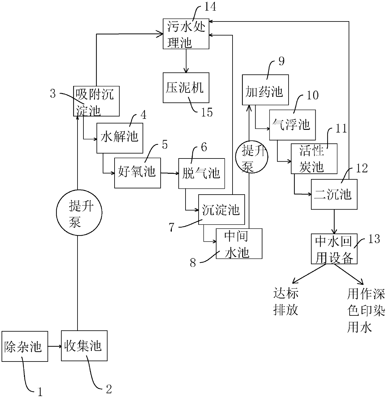
[0045] A sewage treatment system for printing and dyeing, such as figure 1 As shown, its overall process includes:

[0046]The impurity removal pool 1 is equipped with a hair removal machine, and the sewage from the printing and dyeing factory is discharged into the impurity removal pool 1, and the first impurity removal is performed by the hair removal machine, and the fine hairs and larger impurities in the sewage are filtered; Collection pool 2, the sewage after preliminary filtration enters the collection pool 2, the sewage in the impurity removal pool 1 flows into the collection pool 2, and the collection pool 2 is set below the ground; The sewage is sent into the adsorption sedimentation tank 3 located at the highest place through the lifting pump, and the activated sludge is added into the adsorption sedimentation tank 3. The activated sludge ...


PUM


Abstract

The invention discloses a sewage treatment system for dye printing, and aims at solving the problem of poor decomposition effect of a conventional sewage treatment system on organic matters in the sewage. The sewage treatment system is characterized in that according to the sewage treatment system for dye printing, printing sewage is sequentially introduced into a hair fishing pool, a collecting pool, an adsorption precipitation pool, a hydrolyzation pool, an aerobic pool, a degasification pool, a sedimentation pool, a middle water pool, a chemical adding pool, an air floating pool, an activecarbon pool, a secondary sedimentation pool and recycled water reuse equipment. Sewage generated through dye printing is subjected to physical, chemical and biological decomposition. The sewage treatment system for dye printing has the advantages that the decomposition is more thorough and efficient, so that the systemic treatment on the dye printing sewage can be completed; the sewage discharge problem is effectively solved; contribution is made for emission reduction and environment protection.

Description

technical field [0001] The invention relates to the field of sewage treatment, more specifically, it relates to a sewage treatment system for printing and dyeing. Background technique [0002] Printing and dyeing wastewater refers to the wastewater discharged from the pretreatment, dyeing, printing and finishing of cotton, wool, hemp, silk, chemical fiber or blended products. It contains a large amount of complex components such as dyes, sizing agents, and surfactants. It has the characteristics of large chroma, high concentration of organic matter, strong alkalinity, and large changes in water quality and water volume. It is difficult to treat and belongs to difficult-to-treat industrial wastewater. Printing and dyeing wastewater is produced in multiple processes such as washing and dyeing, printing, and sizing. It contains a large amount of organic matter such as dyes, starch, cellulose, lignin, and detergent, as well as inorganic matter such as alkali, sulfide, and variou...

Claims


Application Information

Patent Timeline
IPC IPC(8): C02F9/14C02F103/30
CPCC02F9/00C02F1/283C02F1/24C02F3/02C02F1/66C02F1/5236C02F1/56C02F3/28C02F3/301C02F3/341C02F2001/007C02F2103/30
Inventor 周宸超
Owner 嘉兴市泰石漂染有限公司
Learn More