
Construction method of cast-in-situ concrete-supported prefabricated connecting beam in strip foundation pit

A construction method and connecting beam technology, which is applied in basic structure engineering, excavation, construction, etc., can solve problems such as the inability to realize the repeated use of connecting beams, increase the workload of later chiseling, and the complex force of concrete supports, etc., to achieve The effect of strengthening the restraint, simplifying the stress state, and reducing the workload

Active Publication Date: 2020-05-19
SHANGHAI URBAN CONSTR DESIGN RES INST GRP CO LTD
View PDF5 Cites 0 Cited by
  • Summary
  • Abstract
  • Description
  • Claims
  • Application Information

AI Technical Summary

Problems solved by technology

Therefore, on the one hand, the method of integrally cast-in-place with the concrete support for the connecting beam with relatively simple force and relatively fixed form will make the concrete support more complicated; on the other hand, the repeated use of the connecting beam cannot be realized. It has caused a certain degree of waste, and increased the workload of later chisel removal, reducing production efficiency, which runs counter to the industrial direction of energy saving, emission reduction, and green environmental protection.

Method used


Image

  • Construction method of cast-in-situ concrete-supported prefabricated connecting beam in strip foundation pit
  • Construction method of cast-in-situ concrete-supported prefabricated connecting beam in strip foundation pit
  • Construction method of cast-in-situ concrete-supported prefabricated connecting beam in strip foundation pit

Examples


Embodiment 1

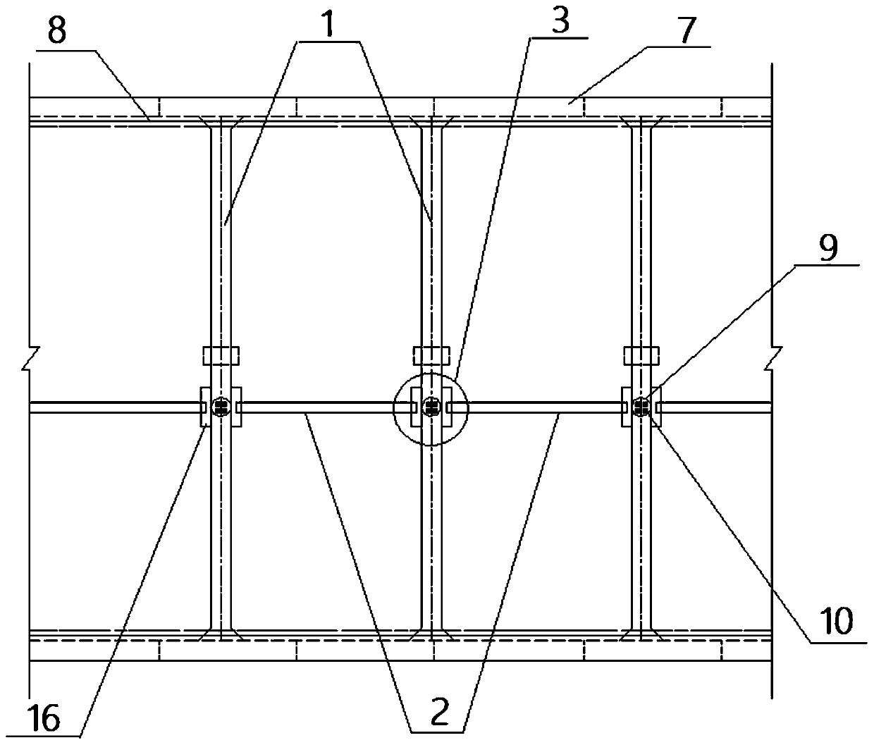
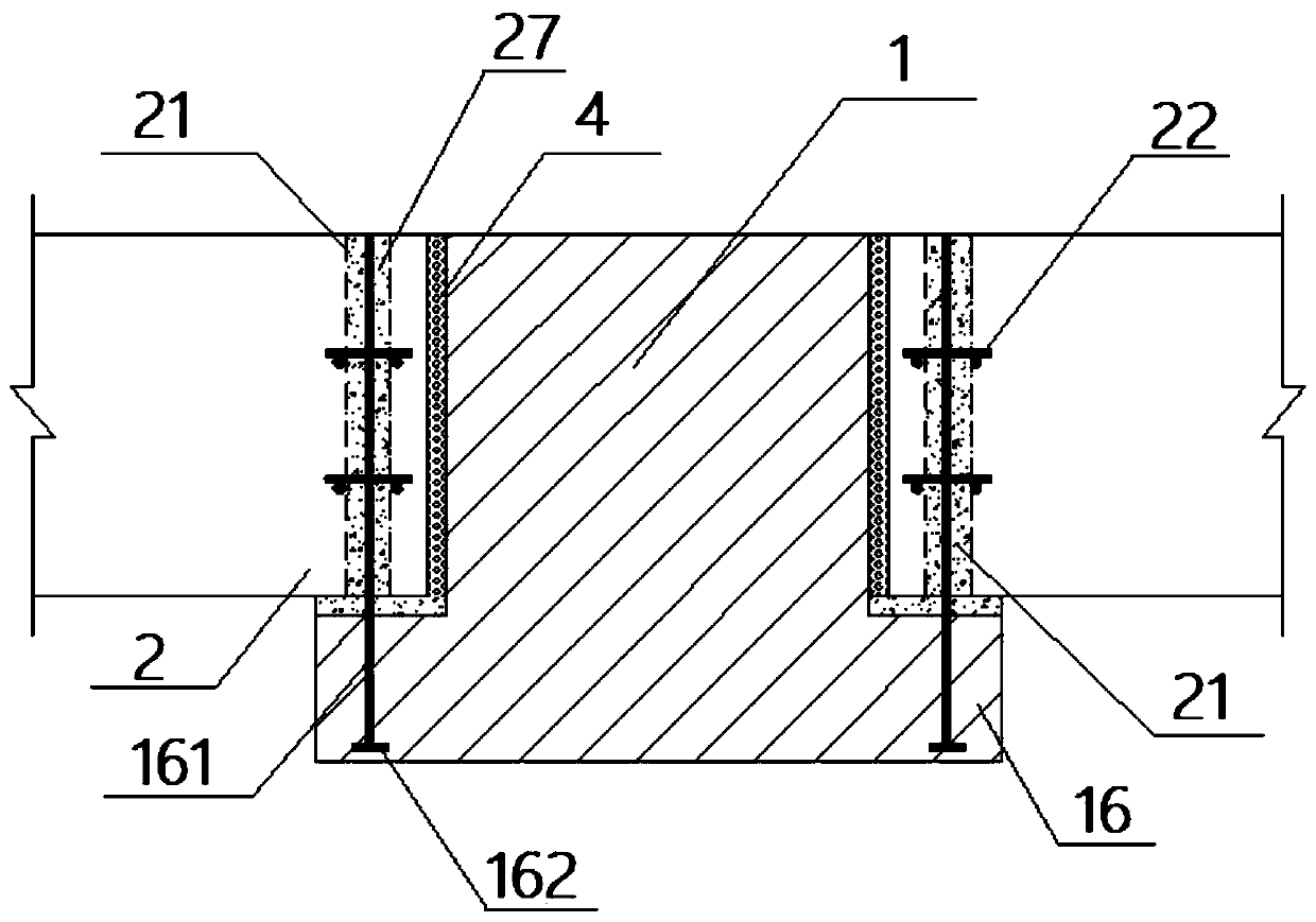
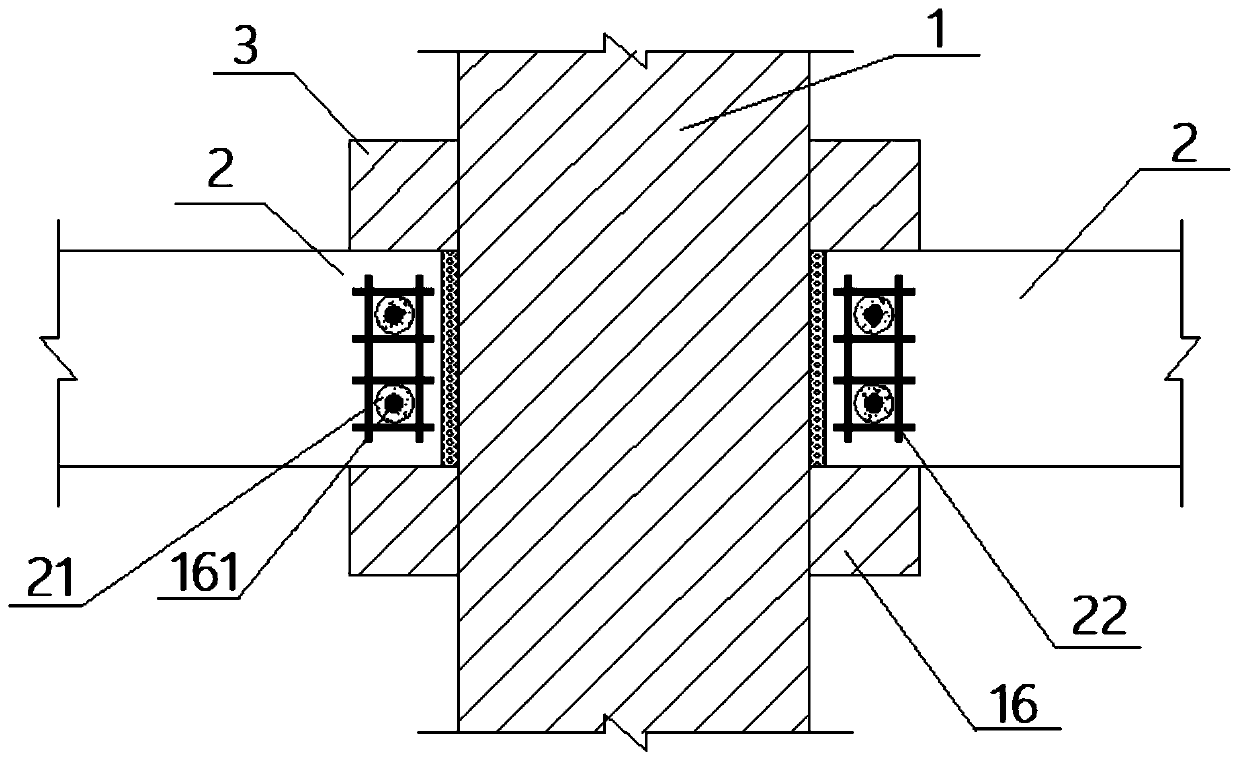
[0034] like Figure 1-3 As shown in the figure, the construction method of the cast-in-situ concrete in the strip foundation pit to support the prefabricated connecting beam, the prefabricated connecting beam in this embodiment is a prefabricated concrete connecting beam, including the following steps:

[0035] A. Factory prefabricated tie beam 2: The length of the precast concrete tie beam 2 is 8-9m, with each increase of 0.1m as a step, the factory prefabricates the precast concrete tie beam 2 with a length of 10 steps in batches. Both ends of the beam 2 are provided with through-bolt insertion holes 21 , and hole edge reinforcing ribs 22 are embedded around the bolt insertion holes 21 .

[0036] B. Construction of foundation pit enclosure structure 7, column piles 9 and temporary steel columns 10;

[0037] The foundation pit enclosure structure is the soil and water retaining structure required for the excavation of the foundation pit. Generally, according to the excavatio...

Embodiment 2

[0043] like Figure 4-6 As shown in the figure, the construction method of the cast-in-situ concrete in the strip foundation pit to support the prefabricated connecting beam, the prefabricated connecting beam in this embodiment is a prefabricated concrete connecting beam, including the following steps:

[0044] A. Factory precast concrete tie beam 2: The length of the precast concrete tie beam 2 is 8-9m, with each increase of 0.1m as a step, the factory prefabricates the precast concrete tie beam 2 with 10 steps of length in batches. Both ends of the tie beam 2 are embedded with tie beam T-shaped embedded parts, and the tie beam T-shaped embedded parts include a tie beam flange 23 and a tie beam web 24 vertically fixed on the tie beam flange 23. The tie beam flange 23 It is vertically embedded in both ends of the precast concrete connecting beam 2, and the reinforcing anchor bars 25 are embedded in the inner side of the connecting beam flange 23; the connecting beam web 24 ext...

Embodiment 3

[0052] like Figure 7-9 As shown, the construction method of the cast-in-situ concrete in the strip foundation pit to support the prefabricated tie beam, in this embodiment, the prefabricated tie beam is a prefabricated steel tie beam, including the following steps:

[0053] A. Factory prefabricated steel tie beam 2: The length of the prefabricated steel tie beam 2 is 8-9m, with each increase of 0.1m as a grade, the factory prefabricates 10 prefabricated steel tie beams 2 in length in batches. In this embodiment , the prefabricated steel tie beam is an I-beam beam 2, a connecting steel plate 26 is provided at both ends of the I-beam beam 2, and a connecting steel plate bolt hole 261 is provided on the connecting steel plate 26, and the arrangement of the steel plate bolt holes 261 corresponds to the pair of Arrangement of the support embedded bolts 15; the I-beam 2 can be formed by section steel or by combining steel plates by welding. In this embodiment, the I-beam 2 is forme...


PUM


Abstract

The invention discloses a construction method of cast-in-place concrete diagonal braces and prefabricated girts of a strip-shaped foundation pit. Through the adoption of the construction method, the prefabricated girts and the cast-in-place concrete diagonal braces of the strip-shaped foundation pit are connected, and it can be guaranteed that internal force of the girts is effectively transmittedthrough a connecting structure; and meanwhile on the premise of meeting the requirements of the aspects of prefabricated component manufacturing, transporting, mounting and the like, the restraint function to the cast-in-place concrete diagonal braces is achieved, and the function of integrality of a first support structure is enhanced. The stress state of the cast-in-place concrete diagonal braces can be more simplified and tend to theoretical analysis, and site operation and fast mounting can be facilitated. Meanwhile, through prefabricated component splicing, the workload of later chiseling away is reduced, recycling of the prefabricated girts is achieved, the production efficiency is improved, and environment protection, energy saving and emission reducing are achieved; and the construction method is especially suitable for the strip-shaped foundation pit in the soft soil area, the building means of underground engineering are effectively expanded, industry technical progress is promoted, and good economic and social benefits are achieved.

Description

technical field [0001] The invention relates to the technical field of foundation pit engineering, in particular to a construction method of a strip foundation pit cast-in-situ concrete braced prefabricated connecting beam. Background technique [0002] In recent years, with the acceleration of urbanization, in large and medium-sized cities with developed economy and heavy traffic, in order to improve regional traffic functions and humanized travel needs, such as pedestrian crossings, subway stations, transfer passages, basements The construction of various types of strip-shaped structures such as channels is in full swing. In some soft soil areas, such as Shanghai, the deformation of the foundation pit due to poor soil quality often causes the first support to be pulled. Therefore, in the evaluation of foundation pits in these areas, the first support is often required to be concrete support, and it is poured simultaneously with the concrete purlin to strengthen the integr...

Claims


Application Information

Patent Timeline
Patent Type & Authority Patents(China)
IPC IPC(8): E02D17/04
CPCE02D17/04
Inventor 张中杰刘书吕培林
Owner SHANGHAI URBAN CONSTR DESIGN RES INST GRP CO LTD
Learn More