High-precision plate shearing machine
A shearing machine, high-precision technology, used in shearing equipment, shearing devices, accessories of shearing machines, etc., can solve the problem that the swing speed of the support frame is difficult to control, affects the quality of sheet material shearing, and cannot guarantee processing accuracy. and other problems to achieve the effect of ensuring shear quality and accuracy, preventing sagging, and optimizing structure
- Summary
- Abstract
- Description
- Claims
- Application Information
AI Technical Summary
Problems solved by technology
Method used
Image

Examples
Embodiment 1
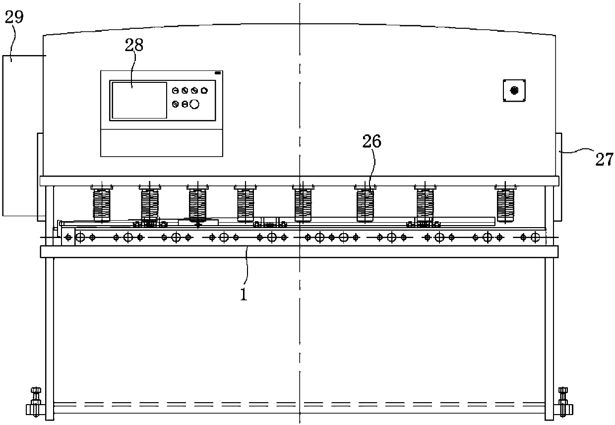
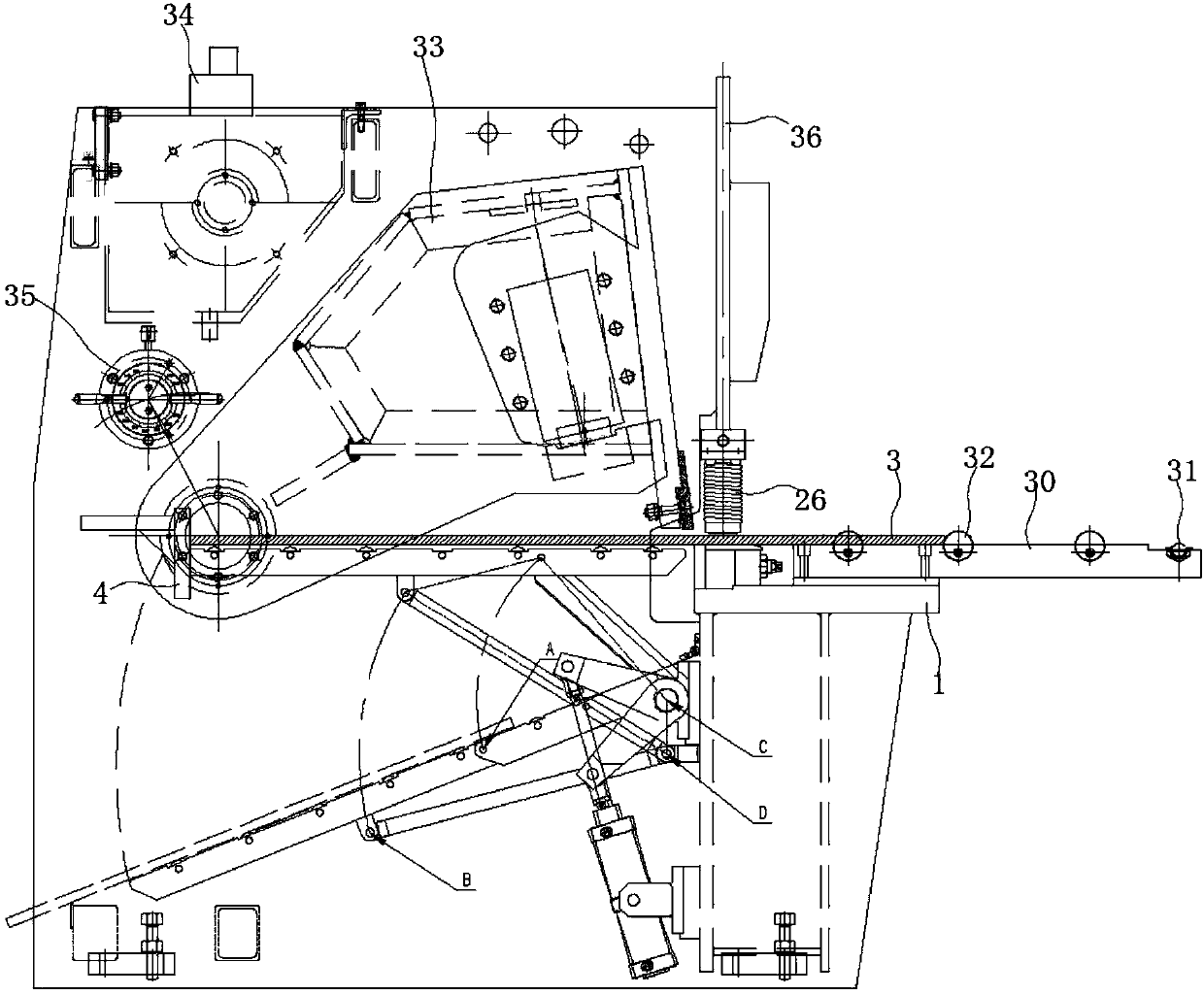
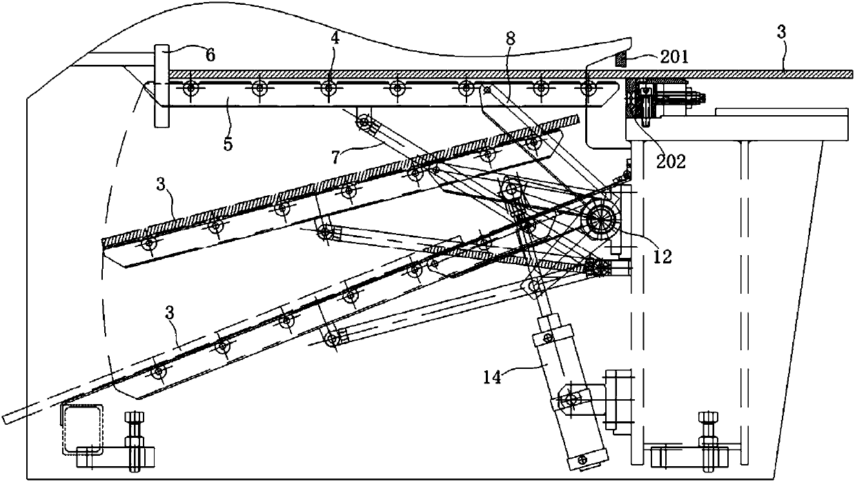
[0042] combine Figure 1-Figure 6 , a high-precision shearing machine of the present embodiment includes a shearing machine frame composed of wall panels on both sides, a front panel 36 and a workbench 1, a shearing mechanism and a material holding mechanism. The shearing mechanism includes an upper knife rest 33, a moving knife 201 installed at the bottom of the upper knife rest 33, and a static knife 202 installed on the top of the workbench 1; the bottom of the front panel 36 is installed with a Binder cylinders 26 evenly distributed at intervals. The above-mentioned supporting mechanism includes a rear supporting device and a pneumatic control system, the rear supporting device is installed on the back side of the shearing machine workbench 1, the pneumatic control system is used to control the up and down swing of the rear supporting device, and the above-mentioned rear supporting device The feeding device comprises a support frame 5, a support rod 7 and a support frame ...
Embodiment 2
[0045] combine Figure 1-Figure 6 , a kind of high-precision plate shearing machine of the present embodiment, its structure is basically the same as embodiment 1, and its difference is: in the present embodiment, the back side of workbench 1 is equipped with transmission shaft 11 through bracket, and one end of support frame 8 is connected with transmission shaft 11 is fixedly connected, the above-mentioned transmission shaft 11 is connected with the cylinder 13 through the swing rod 12, wherein one end of the swing rod 12 is fixedly connected with the transmission shaft 11, and the other end is hinged with the piston rod of the cylinder 13, and the cylinder body of the cylinder 13 is connected through the cylinder bracket 15 is hinged on workbench 1. Through the expansion and contraction of the piston rod of the cylinder 13, the pendulum 12 and the transmission shaft 11 are driven to rotate, thereby driving the support frame 8 to rotate, and under the joint action of the sup...
Embodiment 3
[0049] In conjunction with the accompanying drawings, a high-precision shearing machine of this embodiment has a structure basically the same as that of Embodiment 2, and the difference is that in this embodiment, an inclined laying board 14 is provided on the back of the workbench 1, and the laying board One end of 14 is fixedly connected with workbench 1, and its other end is supported by fixed frame 16. There are gaps between adjacent laying boards 14 , and the above-mentioned brackets 5 , support frames 8 and swing rods 12 are all correspondingly arranged in the gaps between adjacent laying boards 14 .
[0050] In this embodiment, the support frame 8 is designed as a U-shaped frame structure, and the width of the U-shaped groove on its surface matches the width of the support frame 5 . When the support frame 5 swings to the highest position, its upper surface is flush with the surface of the workbench 1, and the distance d between the support frame 5 and the static knife 2...
PUM
 Abstract
Description
Claims
Application Information
 - R&D
- Intellectual Property
- Life Sciences
- Materials
- Tech Scout
- Unparalleled Data Quality
- Higher Quality Content
- 60% Fewer Hallucinations
Browse by: Latest US Patents, China's latest patents, Technical Efficacy Thesaurus, Application Domain, Technology Topic, Popular Technical Reports.
© 2025 PatSnap. All rights reserved.Legal|Privacy policy|Modern Slavery Act Transparency Statement|Sitemap|About US| Contact US: help@patsnap.com