Four-point pneumatic supporting device and method for plate shearing machine
A four-point, shearing machine technology, used in shearing devices, accessories of shearing machines, shearing machine equipment, etc., can solve the problems of inability to guarantee processing accuracy, easy insertion of sheets, manual removal, etc., to ensure shearing. The effect of cutting quality and precision, reducing the gap between the supporting materials, and facilitating the taking of materials
- Summary
- Abstract
- Description
- Claims
- Application Information
AI Technical Summary
Problems solved by technology
Method used
Image

Examples
Embodiment 1
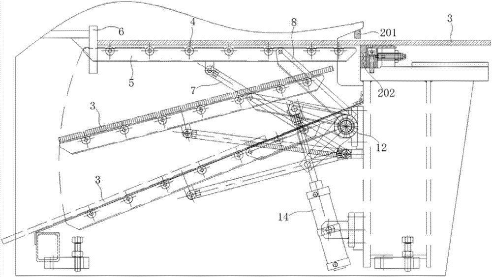
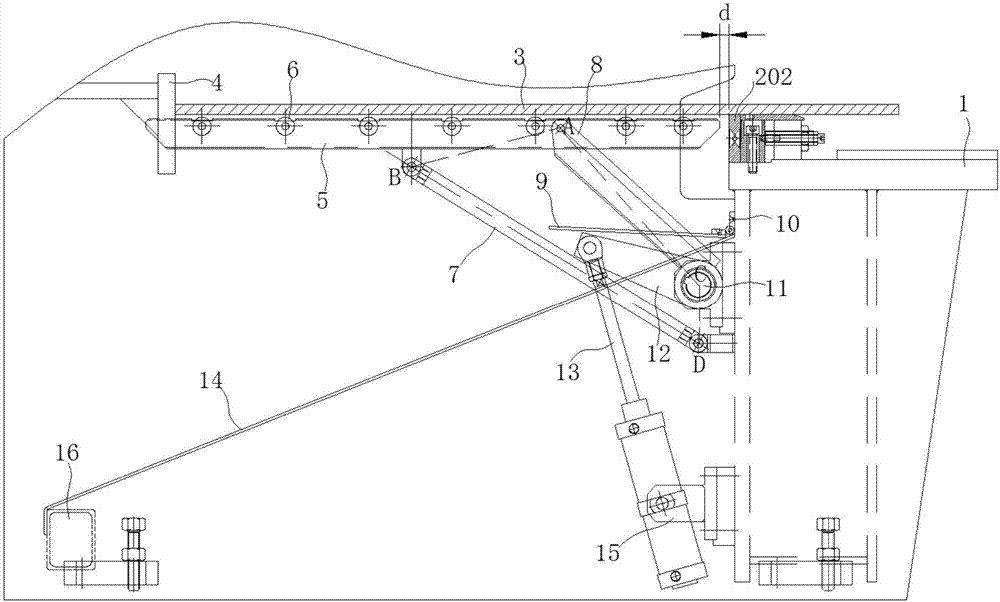
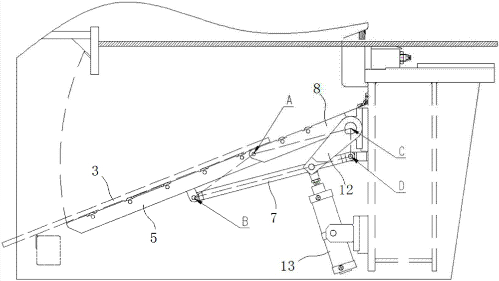
[0046] combine Figure 1-Figure 4 , a four-point pneumatic supporting device for a plate shearing machine in this embodiment includes a supporting frame 5, a supporting rod 7 and a supporting frame 8, wherein one end of the supporting rod 7 and the supporting frame 8 is connected to the supporting frame 5 Hinged, the other ends of the support rod 7 and the support frame 8 are hinged with the workbench 1, and the swing of the support rod 7 and the support frame 8 drives the support frame 5 to swing up and down, thereby realizing the support and unloading of the sheet material 3 to be processed. material. The material supporting device of this embodiment can set the length of the material supporting frame 5 according to the distance between the rear baffle and the workbench, so that the material supporting distance between the material supporting frame 5 and the blade can be effectively reduced to 8- 12mm, compared with the existing supporting device, the supporting gap is grea...
Embodiment 2
[0048] combine Figure 1-Figure 4 , a four-point pneumatic material support device for a shearing machine in this embodiment, its structure is basically the same as in Embodiment 1, the difference is that: the back of the workbench 1 is equipped with a transmission shaft 11 through a bracket, and the transmission shaft 11 is connected to the The driving device is connected, and one end of the support frame 8 is fixedly connected with the transmission shaft 11 . The driving device drives the transmission shaft 11 to rotate, thereby driving the support frame 8 to rotate, and under the joint action of the support frame 8 and the support rod 7, the support frame 5 is driven to swing up and down. Through the function of the transmission shaft 11, the entire material supporting device can be driven to perform synchronous movement, thereby ensuring the shearing accuracy of the plate and reducing errors.
[0049] The above-mentioned support frame 8 and support rod 7 are the key compo...
Embodiment 3
[0052] combine Figure 1-Figure 4 , a four-point pneumatic material support device for a shearing machine of this embodiment, its structure is basically the same as that of Embodiment 2, the difference is that the driving device of this embodiment includes a swing rod 12 and a cylinder 13, wherein one end of the swing rod 12 It is fixedly connected with the transmission shaft 11 , and its other end is hinged with the piston rod of the cylinder 13 , and the cylinder body of the cylinder 13 is hinged to the workbench 1 through the cylinder bracket 15 . The telescopic drive of the piston rod of the cylinder 13 drives the swing rod 12 to rotate, thereby driving the transmission shaft 11 to rotate, and further driving the support frame 5 to swing up and down.
[0053] In this embodiment, the distance between point A and the end of the support frame 5 near the workbench 1 is 1 / 3 of the total length of the support frame 5, and the distance between point B and the end of the support f...
PUM
 Abstract
Description
Claims
Application Information
 - R&D
- Intellectual Property
- Life Sciences
- Materials
- Tech Scout
- Unparalleled Data Quality
- Higher Quality Content
- 60% Fewer Hallucinations
Browse by: Latest US Patents, China's latest patents, Technical Efficacy Thesaurus, Application Domain, Technology Topic, Popular Technical Reports.
© 2025 PatSnap. All rights reserved.Legal|Privacy policy|Modern Slavery Act Transparency Statement|Sitemap|About US| Contact US: help@patsnap.com