
Metal waste scrap and waste liquid separation and collection device of center lathe

A common lathe and waste liquid separation technology, applied in the application field of lathe waste chip treatment equipment, can solve the problems of inconvenience for cleaning personnel to handle, mixing of waste chips and waste liquid, low collection efficiency, etc. Improve cleaning efficiency

Inactive Publication Date: 2018-03-16
镇江市丹徒区石马机械铸造厂
View PDF0 Cites 14 Cited by
  • Summary
  • Abstract
  • Description
  • Claims
  • Application Information

AI Technical Summary

Problems solved by technology

[0003] There are many problems in the processing of lathe waste. For example, the existing collection and treatment device for lathe waste is relatively simple. Some lathes set up a collection plate at the bottom for collection. The collection efficiency is relatively low, and it is not easy for cleaning personnel to handle. For some lathes that require coolant for accelerated cooling, waste chips and waste liquid are often mixed, which is difficult to handle. Special cleaning personnel need to be arranged to clean up, which is not easy to use

Method used


Image

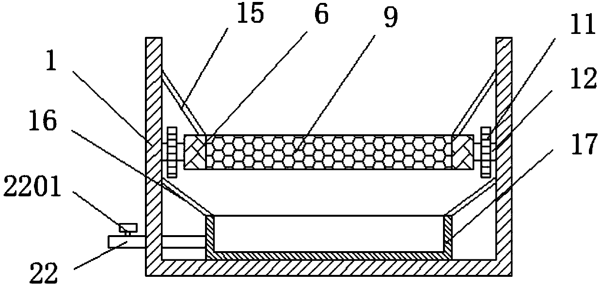
  • Metal waste scrap and waste liquid separation and collection device of center lathe
  • Metal waste scrap and waste liquid separation and collection device of center lathe
  • Metal waste scrap and waste liquid separation and collection device of center lathe

Examples


Embodiment Construction

[0021] The following will clearly and completely describe the technical solutions in the embodiments of the present invention with reference to the accompanying drawings in the embodiments of the present invention. Obviously, the described embodiments are only some, not all, embodiments of the present invention. Based on the embodiments of the present invention, all other embodiments obtained by persons of ordinary skill in the art without making creative efforts belong to the protection scope of the present invention.

[0022] see Figure 1-3 As shown, a common lathe metal waste and waste liquid separation and collection device includes a main housing 1, a waste liquid tank 17, and a metal storage tank 21. One side of the main housing 1 is fixedly connected to a fixing frame 2, and the fixing frame 2. The motor 3 is fixedly connected inside to realize the stable fixing of the motor 3; the output end of the motor 3 is connected to the first rotating shaft 4, and the surface of...


PUM


Abstract

The invention discloses a metal waste scrap and waste liquid separation and collection device of a center lathe. The metal waste scrap and waste liquid separation and collection device of the center lathe comprises a main shell, a fixing frame, a motor, a first rotary shaft, a first roller, a conveying belt, a second roller, a second rotary shaft, a metal filtering net, big gears, a small gear, arotary rod, a brush cylinder, brush bristles, first inclined boards, a second inclined board, a waste liquid tank, a fixing column, a sliding groove, an electric heating board, a vibration motor, a metal containing tank, a liquid discharging pipe and a liquid discharging valve. The metal waste scrap and waste liquid separation and collection device of the center lathe is reasonable in structure; the interior of the conveying belt is in clamped connection with the metal filtering net, so that separation of metal waste scraps from waste water is achieved; through the rotation function of the conveying belt, waste residues are convenient to transfer, better processing by cleaning workers is conveniently ensured, the cleaning efficiency is improved, and usage is facilitated; and through mutualcooperation action of the second rotary shaft, the big gears, the small gear, the rotary rod, the brush cylinder and the brush bristles, metal waste residues on the surface of the metal filtering netare removed.

Description

technical field [0001] The invention relates to a separation and collection device, in particular to a separation and collection device for common lathe metal waste and waste liquid, and belongs to the technical field of application of lathe waste treatment equipment. Background technique [0002] Ordinary lathes are horizontal lathes that can perform multiple processes on various types of workpieces such as shafts, disks, and rings. Drilling, reaming, tapping and knurling, etc., will generate a lot of waste chips during the processing of ordinary lathes, which need to be treated regularly. [0003] There are many problems in the processing of lathe waste. For example, the existing collection and treatment device for lathe waste is relatively simple. Some lathes set up a collection plate at the bottom for collection. The collection efficiency is relatively low, and it is not easy for cleaning personnel to handle. For some lathes that require coolant for accelerated cooling,...

Claims


Application Information

Patent Timeline
IPC IPC(8): B23B25/00B23Q11/00B01D33/00B01D33/04
CPCB01D33/00B01D33/04B23B25/00B23Q11/00
Inventor 任革富
Owner 镇江市丹徒区石马机械铸造厂
Learn More