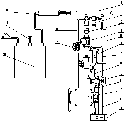
Chest drainage device
A thoracic cavity and hydraulic cylinder technology, applied in the field of medical drainage devices, can solve the problems of increased pain for patients, inconvenience for doctors, inability to further measure and control changes in thoracic pressure of drainage speed, and achieve the effect of alleviating pain
- Summary
- Abstract
- Description
- Claims
- Application Information
AI Technical Summary
Problems solved by technology
Method used
Image
Examples
Embodiment 1
[0022] A chest drainage device such as figure 1 shown. The drainage device at least includes an oil cylinder 1, a hydraulic pump 2, a two-position four-way solenoid valve 3, an incremental digital pressure reducing valve 4, a direct control pressure reducing pressure compensation digital speed control valve 5, a direct control pressure reducing type Pressure compensation digital speed control valve 5, flow rate sensor 6, one-way valve 7, double-acting single-piston rod hydraulic cylinder 9, plunger barrel 10, diverter 12 and control unit. Preferably, the air guide 12 is also provided with an exhaust hole 13 and a conduit 14 .
[0023] The oil cylinder 1 is connected with the hydraulic pump 2 through a pipeline. The oil cylinder 1 is connected with the incremental digital decompression valve 4 through the second oil pipe 16 . The oil cylinder 1 is connected with the two-position four-way solenoid valve 3 through a third oil pipe 17 . Described oil cylinder links to each oth...
PUM
 Abstract
Description
Claims
Application Information
 - R&D Engineer
- R&D Manager
- IP Professional
- Industry Leading Data Capabilities
- Powerful AI technology
- Patent DNA Extraction
Browse by: Latest US Patents, China's latest patents, Technical Efficacy Thesaurus, Application Domain, Technology Topic, Popular Technical Reports.
© 2024 PatSnap. All rights reserved.Legal|Privacy policy|Modern Slavery Act Transparency Statement|Sitemap|About US| Contact US: help@patsnap.com


