
Infrared panorama generation method based on infrared thermal imaging system

An infrared thermal imaging and panorama technology, which is applied in the details, image enhancement, and image analysis involving image stitching to achieve the effect of eliminating stitching gaps, high precision, and improving computing speed.

Inactive Publication Date: 2018-03-09
NANJING UNIV OF SCI & TECH
View PDF4 Cites 19 Cited by
  • Summary
  • Abstract
  • Description
  • Claims
  • Application Information

AI Technical Summary

Problems solved by technology

[0006] As can be seen from the above, there is no good method for generating infrared panoramas based on infrared thermal imaging systems in the prior art

Method used


Image

  • Infrared panorama generation method based on infrared thermal imaging system
  • Infrared panorama generation method based on infrared thermal imaging system
  • Infrared panorama generation method based on infrared thermal imaging system

Examples


Embodiment

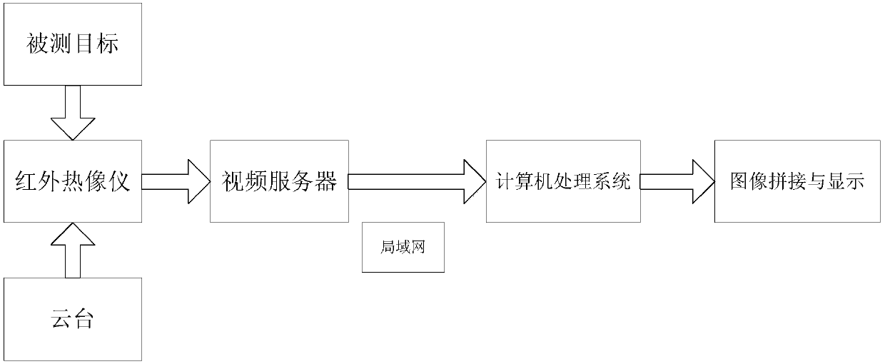
[0050] First turn on the thermal imaging camera and connect it to the image acquisition system to prepare for taking pictures. Then set the gimbal to take a picture every 20 degrees, and take two pictures in total. Figure 4 and Figure 5 . The size of these two images is the same, both are 320*640 in size, and the images taken later are transferred to the computer processing system through the video server and local area network, and the processing platform is visual studio 2010+opencv 2.4.10.

[0051] Next comes the image processing step.

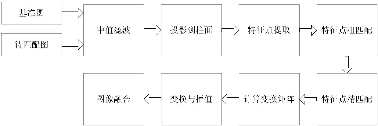
[0052] Step 1: The two images are processed by median filtering to eliminate unnecessary noise, and the window size of median filtering is 3*3. The principle of median filtering is: if the pixel value of a certain pixel in the image is I(x, y), then in the 3*3 field around (x, y), the pixel values ​​​​of 9 points in the neighborhood are respectively Sort from small to large, take the pixel value of the fifth point.

[0053] Step 2: P...


PUM


Abstract

The invention discloses an infrared panorama generation method based on an infrared thermal imaging system. The method comprises the steps that images undergo preprocessing of denoising, coordinate transform and the like; a fast operator combined with a scale space is used to extract feature points; an improved sift feature descriptor is used to generate a feature point descriptor; a distance ratio method is used to roughly match the feature points of two images; and a random sample consensus algorithm (RANSAC) is used to further refine matched points to acquire a transformation matrix betweentwo images; and after an image to be matched is transformed into the coordinate of a reference image, a fade-in and fade-out weighted average method is used to carry out image fusion to stitch two images. The infrared panorama provided by the invention solves the problem of the narrow angle of view of a conventional infrared thermal imager, and has broad prospects and applications in electric power, remote sensing, medicine, agriculture and forestry.

Description

technical field [0001] The invention relates to the fields of image processing and machine vision, in particular to a method for generating an infrared panorama based on an infrared thermal imaging system. Background technique [0002] Any object with a temperature above absolute zero radiates energy in the form of electromagnetic waves. Among the various wavelengths included in radiant energy, those with wavelengths ranging from 0.76 to 1000 microns are called infrared light waves. According to Planck's black body radiation law, we can conclude that the radiation ability of an object increases with the increase of temperature, and the radiation wavelength moves to the short wave direction as the temperature increases. It can also be seen from the Stephen-Boltzmann law that as long as there is a small change in temperature, the radiation power emitted by the object will change greatly. It is precisely because the energy of infrared radiation is directly proportional to the...

Claims


Application Information

Patent Timeline
Patent Type & Authority Applications(China)
IPC IPC(8): G06T5/00G06T5/50G06T7/33
CPCG06T5/50G06T2207/20221G06T2200/32G06T2207/10048G06T2207/20016G06T5/70
Inventor 黄成杜静涵宋跃磊陈嘉金威王力立徐志良
Owner NANJING UNIV OF SCI & TECH
Learn More