High-speed visual detection equipment of soft magnetic core

A visual inspection and magnetic core technology, which is applied in the direction of measuring devices, optical testing of flaws/defects, and material analysis through optical means, can solve problems such as the inability to meet the detection speed detection speed requirements, complex detection process, and low degree of automation. Achieve the effect of all-round high-speed inspection, advanced visual algorithm and reasonable design

Inactive Publication Date: 2018-03-09
SYNEY ELECTRIC HANGZHOU CO LTD
View PDF1 Cites 4 Cited by
  • Summary
  • Abstract
  • Description
  • Claims
  • Application Information

AI Technical Summary

Problems solved by technology

However, the production process of soft magnetic metal oxide workpieces is complicated, and defects such as cracks, broken corners, stains, and excessive dimensional errors will inevitably be introduced.
Therefore, the defect detection of soft magnetic workpieces is particularly important. Traditional detection methods include manual detection, eddy current detection, and penetration detection. These methods have disadvantages such as low efficiency, complicated detection process, and low degree of automation. The key dimension information of the workpiece cannot be obtained
Patent 201510787229.9 discloses a multi-station transmission camera mechanism for automatic detection of soft magnetic cores. This mechanism uses intermittent rotation devices to realize the cooperation of detection modules, workpiece calibration modules, and kicking modules. However, this method requires a turntable Intermittent start and stop, unable to meet the detection rate requirement of more than 1200 per minute, and the method disclosed in the literature includes four sets of camera light source systems, which cannot complete the detection and measurement of the six sides of the workpiece

Method used


Image

  • High-speed visual detection equipment of soft magnetic core
  • High-speed visual detection equipment of soft magnetic core
  • High-speed visual detection equipment of soft magnetic core

Examples


Embodiment Construction

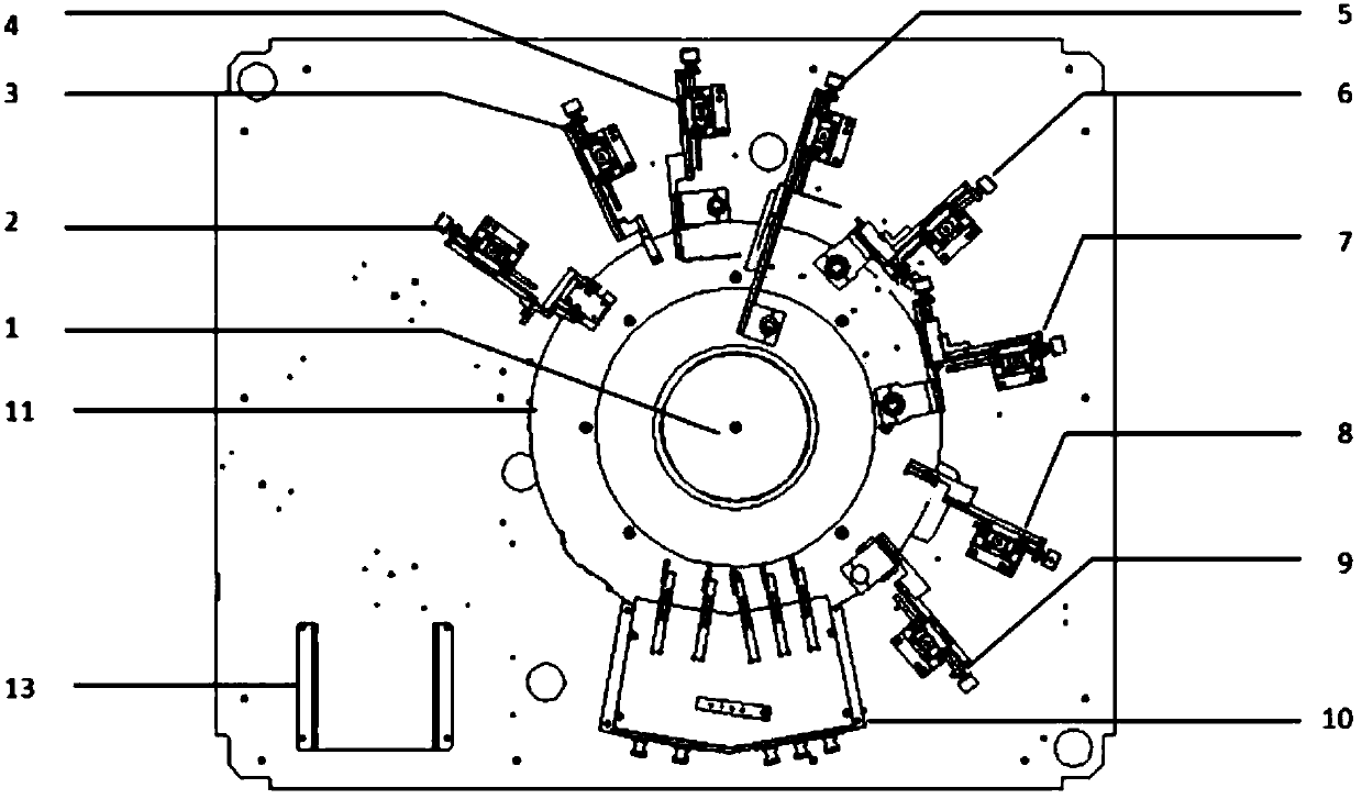
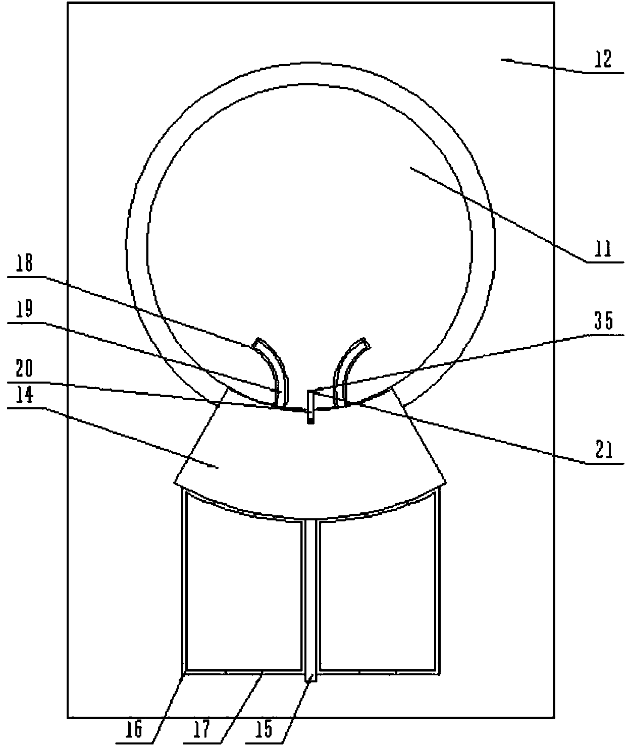
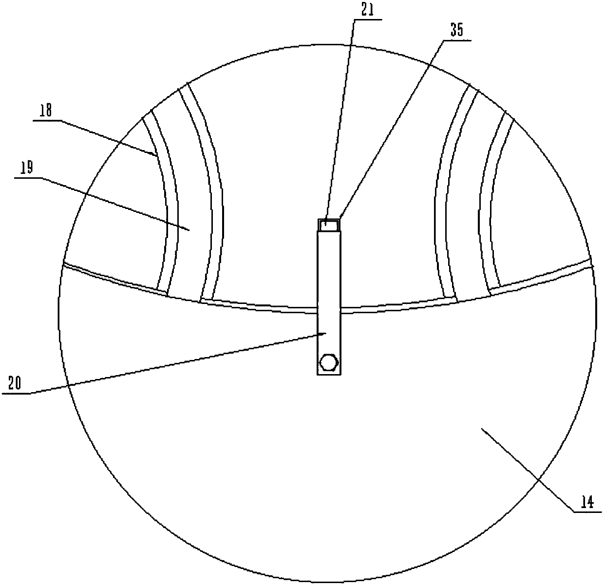
[0019] The present invention will be specifically described below in conjunction with the accompanying drawings, such as Figure 1-6 As shown in the figure, a high-speed visual inspection equipment for a soft magnetic core includes a device table (12), and the device table (12) is provided with a feeding turntable (11), a servo drive unit (1), and a workpiece posture adjustment module (2), photoelectric switch (3), front station CCD and light source module (4), rear station CCD and light source module (5), left station CCD and light source module (6), right station CCD and light source module (7), an upper station CCD and a light source module (8), a lower station CCD and a light source module (9) and an industrial computer (13), the feeding turntable (11) is arranged on the device table (12) through a rotating fixing mechanism ), the feeding turntable (11) is provided with a kicking module station (10), and the kicking module station (10) is fixed on the feeding turntable (11...


PUM


Abstract

The invention discloses a high-speed visual detection device for soft magnetic cores, which includes a device table, on which a feed turntable, a servo drive unit, a workpiece position adjustment module, a photoelectric switch, a front station CCD and a light source module are arranged. , rear station CCD and light source module, left station CCD and light source module, right station CCD and light source module, upper station CCD and light source module, lower station CCD and light source module and industrial computer, the feeding carousel passes through The rotation fixing mechanism is arranged on the device table, and the kicking module station is provided on the feeding turntable, and the kicking module station is fixed on the feeding turntable by a buckle mechanism, and the cross section of the kicking block body is The fan-shaped structure and the angle formed after the opposite two sides are extended are 60°. The invention has the advantages of simple structure and strong practicability.

Description

technical field [0001] The invention relates to the field of automatic production of soft magnetic cores, in particular to a high-speed visual inspection device for soft magnetic cores. Background technique [0002] With the rapid growth of demand for various consumer electronics and the rapid development of the soft magnetic metal oxide industry, China has gradually developed into the world's largest producer and exporter of soft magnetic metal oxides. However, the production process of soft magnetic metal oxide workpieces is complicated, and defects such as cracks, broken corners, stains, and excessive dimensional errors will inevitably be introduced. Therefore, the defect detection of soft magnetic workpieces is particularly important. The traditional detection methods include manual detection method, eddy current detection method and penetration detection method. These methods all have the disadvantages of low efficiency, complex detection process and low degree of autom...

Claims


Application Information

Patent Timeline
IPC IPC(8): G01N21/88G01N21/01
CPCG01N21/88G01N21/01
Inventor 刘涛万仁全王凌云
Owner SYNEY ELECTRIC HANGZHOU CO LTD
Why Eureka
Try Eureka