
Electromagnetic actuator

A technology of electromagnetic actuators and permanent magnets, which is applied in the direction of magnetic springs, springs/shock absorbers, springs, etc., and can solve problems that affect the electromagnetic compatibility of actuators, limit the power of actuators, and limit engineering applications.

Active Publication Date: 2018-03-09
ZHUZHOU TIMES NEW MATERIALS TECH
View PDF7 Cites 14 Cited by
  • Summary
  • Abstract
  • Description
  • Claims
  • Application Information

AI Technical Summary

Problems solved by technology

Otherwise, heat will limit the force that the actuator can generate
Secondly, due to the deficiencies in the structural design, the magnetic flux leakage of the actuator is large, which affects the electromagnetic compatibility of the actuator, which limits the engineering application.

Method used

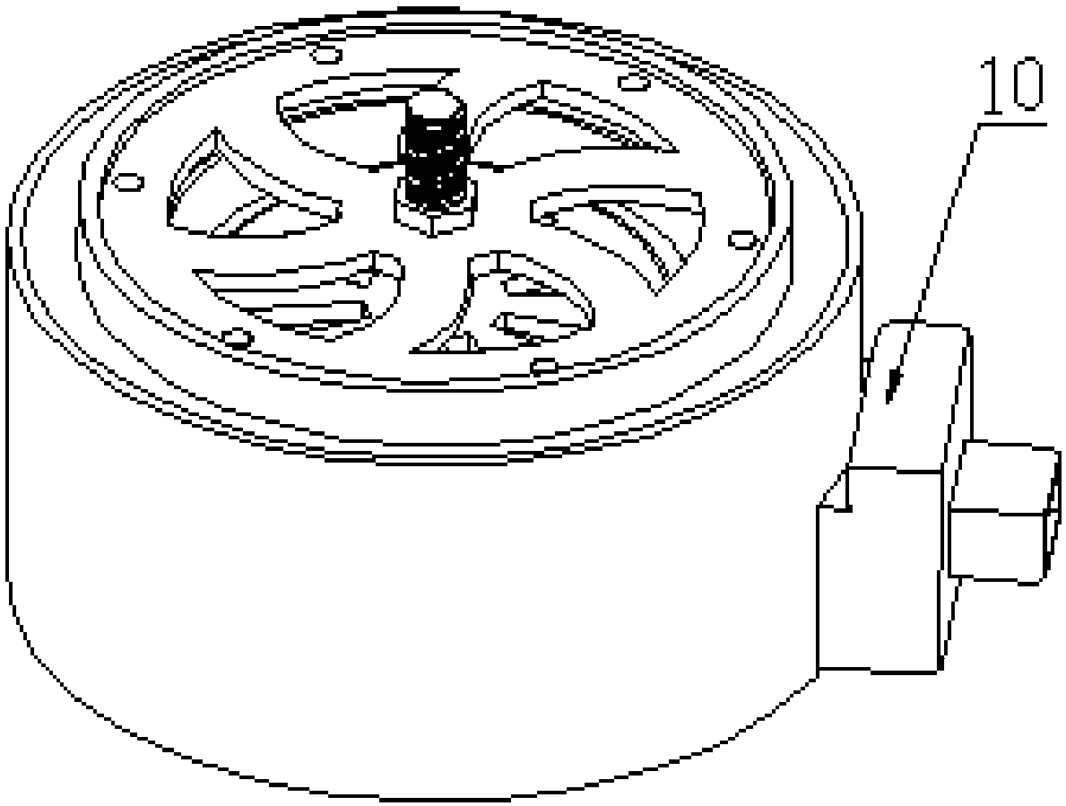
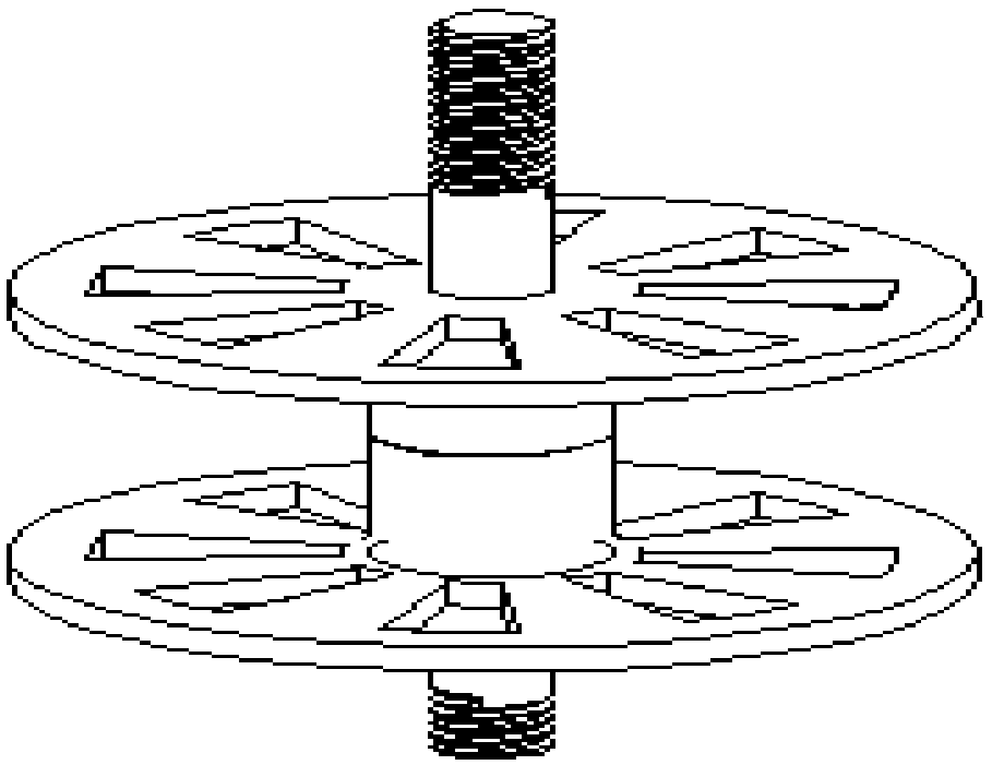

Image

  • Electromagnetic actuator
  • Electromagnetic actuator
  • Electromagnetic actuator

Examples


Embodiment Construction

[0026] In order to make the object, technical solution and advantages of the present invention clearer, the embodiments of the present invention will be further described in detail below in conjunction with the accompanying drawings.

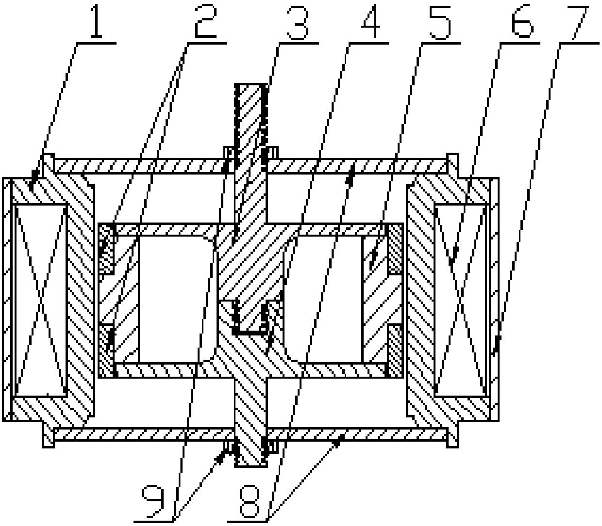
[0027] figure 1 A cross-sectional view of the novel high-efficiency electromagnetic actuator of the present invention is shown.

[0028] Specifically, as figure 1 As shown, the electromagnetic actuator includes an outer sleeve 7 , a support frame 1 , a coil 6 , a vibrator assembly and a plurality of spring pieces 8 . Wherein, the outer sleeve 7 is made of non-magnetic material.

[0029] The support frame 1 is arranged in the outer sleeve 7, and its upper and lower sides are provided with mutually symmetrical annular inner steps for placing spring pieces. In one example, the support frame is fixedly installed with the outer sleeve by press-fitting, so that the outer side of the support frame 1 and the inner wall of the outer sleeve 7 jointly d...


PUM


Abstract

The invention provides an electromagnetic actuator, comprising: an outer sleeve (7) of magnetically non-permeable material; a support frame (1) arranged in the outer sleeve, wherein a closed inner cavity is jointly defined by the outer side of the support frame and the inner wall of the outer barrel (7); a coil (6) arranged in the inner cavity; a vibrator component arranged in the support frame (1) in the outer sleeve and including upper and lower circular permanent magnets (2), a permanent magnet skeleton (5) to support the circular permanent magnets (2) and first and second connection rods (3 and 4) fixedly connected with the permanent magnet skeleton, wherein the permanent magnets are symmetrically distributed on the permanent magnet skeleton in a manner of uniform pole distribution directions, the direction of a magnetic field produced by the permanent magnets magnetized and the direction of a magnetic field produced by a coil electrified form a certain included angle; two or moresprings (8) arranged at the top and bottom of the support frame (1) respectively and fixedly connected with the vibrator component after the first and second connection rods (3 and 4) are passed through the centers of the springs.

Description

technical field [0001] The invention relates to the field of electrical components, in particular to an electromagnetic actuator. Background technique [0002] Due to the high reliability of the passive vibration reduction system, and considering the characteristics of the excitation force and other factors, generally the passive control system is mainly used to reduce the vibration of the vibration source. However, with the continuous development of science and technology, the vibration requirements for the environment and equipment are getting higher and higher, and passive vibration reduction can no longer fully meet people's needs. Therefore, more and more attention has been paid to active vibration control through active components. [0003] Actuator is an important device for active vibration control. Its function is to change the vibration response of the system by applying control force to the control object according to the determined control law. Because the powe...

Claims


Application Information

Patent Timeline
Patent Type & Authority Applications(China)
IPC IPC(8): F16F6/00
CPCF16F6/00
Inventor 刘建勋昌耀鹏涂奉臣马秋成
Owner ZHUZHOU TIMES NEW MATERIALS TECH
Learn More