
Pump body structure of self-priming pump with split liquid storage chamber and gas-liquid separating chamber

A technology of gas-liquid separation and liquid storage chamber, which is applied to components of pumping devices for elastic fluids, liquid fuel engines, pumps, etc., and can solve the problems of high rejection rate of pump body castings, complex structure of pump body, and poor casting process To improve the casting process, optimize the structure of the pump body, and reduce the scrap rate

Inactive Publication Date: 2018-03-09
QINGDAO RUNCHENG VEHICLE FITTINGS CO LTD
View PDF0 Cites 0 Cited by
  • Summary
  • Abstract
  • Description
  • Claims
  • Application Information

AI Technical Summary

Problems solved by technology

[0004] The technical problem to be solved and the technical task proposed by the present invention are to overcome the defects of the existing integrated self-priming pump, such as complex pump body structure, poor casting process, high reject rate of pump body castings, and low production efficiency, and provide a liquid storage Self-priming pump body structure with separate chamber and gas-liquid separation chamber

Method used


Image

  • Pump body structure of self-priming pump with split liquid storage chamber and gas-liquid separating chamber
  • Pump body structure of self-priming pump with split liquid storage chamber and gas-liquid separating chamber

Examples


Embodiment Construction

[0012] The present invention will be further described below with reference to the accompanying drawings.

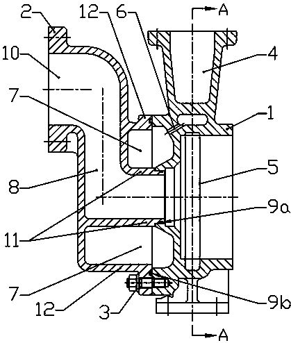
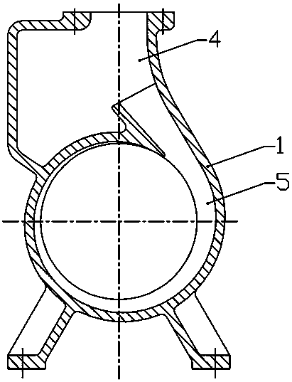
[0013] The self-priming pump body structure of the liquid storage chamber and the gas-liquid separation chamber of the present invention are separated, such as figure 1 , 2 As shown, it includes an inlet 10, a flow channel 8, a volute chamber 5, a gas-liquid separation chamber 4, a liquid storage chamber 7, and a return hole 6, and the inlet 10, the flow channel 8, the volute chamber 5, and the gas-liquid separation chamber 4 are connected in sequence. The return hole 6 communicates with the gas-liquid separation chamber 4 and the liquid storage chamber 7. The pump body structure is formed by connecting the inlet cavity 2 and the pump body 1 through fasteners 3. The inlet 10, the flow channel 8, and the liquid storage chamber 7 are located in the On the inlet cavity 2, the volute 5, the gas-liquid separation chamber 4, and the return hole 6 are set on the pump body 1. ...


PUM


Abstract

The invention discloses a pump body structure of a self-priming pump in which a liquid storage chamber and a gas-liquid separation chamber are separated, which belongs to the pump structure. The pump body structure of the existing integrated self-priming pump is complicated, the casting process is poor, and the rejection rate of the pump body castings is low. High, low production efficiency, the pump body structure of the present invention is formed by connecting the inlet cavity and the pump body through fasteners, the inlet, flow channel, and liquid storage chamber are arranged on the inlet cavity, and the volute chamber, gas-liquid separation chamber, The return hole is set on the pump body. On the basis of satisfying the self-priming function of the self-priming pump, the pump body structure of the self-priming pump is optimized, the casting process of the pump body is improved, the reject rate of the pump body casting is reduced, and the production is improved. efficiency and reduce production costs.

Description

technical field [0001] The invention belongs to a pump structure, in particular to a self-priming pump body structure in which a liquid storage chamber and a gas-liquid separation chamber are separated. Background technique [0002] The traditional self-priming pump body structure is: an integrated pump body structure including a gas-liquid separation chamber, a volute, a liquid storage chamber and an S-shaped flow channel. The disadvantages are that the pump body structure is complex and the casting process of the pump body is poor. , the rejection rate of pump body castings is high, and the production [0003] The efficiency is low and the relative production cost is high. Contents of the invention [0004] The technical problem to be solved and the technical task proposed by the present invention are to overcome the defects of the existing integrated self-priming pump, such as the complex structure of the pump body, poor casting process, high rejection rate of pump bod...

Claims


Application Information

Patent Timeline
IPC IPC(8): F04D29/42F04D9/02
CPCF04D29/426F04D9/02
Inventor 穆卫霞于军委穆平成
Owner QINGDAO RUNCHENG VEHICLE FITTINGS CO LTD
Learn More