
Rocker for articulated industrial robots and articulated industrial robots

An industrial robot and joint-type technology, which is applied in the direction of manipulators, manufacturing tools, and program-controlled manipulators, can solve the problems of reducing casting performance, large thickness changes, and increasing the difficulty of demoulding, so as to improve casting and processing performance and enhance Strength and rigidity performance, effect of reducing manufacturing cost

Active Publication Date: 2017-12-12
昆山华恒机器人有限公司 +1
View PDF1 Cites 0 Cited by
  • Summary
  • Abstract
  • Description
  • Claims
  • Application Information

AI Technical Summary

Problems solved by technology

On the one hand, the overall design of the rocker adopts a non-open outer envelope structure, which increases the difficulty of the casting process, that is, increases the design difficulty and cost of the internal sand core, and also increases the difficulty of demoulding, which affects production efficiency
On the other hand, the positioning boss is located at the upper and lower places on the side where the rocker is connected to the boom. The boss is protruding in a large volume, and the outer envelope design or solid block design is adopted, which also increases the difficulty of designing the internal forming sand core. , In addition, the solid block will reduce the performance of the local casting here, and the thickness will vary greatly, which will easily cause casting defects such as shrinkage cavity and looseness; this is the key area where the rocker parts are stressed, and the defects in casting performance will weaken the rocker. Strength and Stiffness Properties

Method used


Image

  • Rocker for articulated industrial robots and articulated industrial robots
  • Rocker for articulated industrial robots and articulated industrial robots
  • Rocker for articulated industrial robots and articulated industrial robots

Examples


Embodiment Construction

[0030] In order to make the object, technical solution and advantages of the present invention clearer, the present invention will be described in detail below in conjunction with the accompanying drawings and specific embodiments.

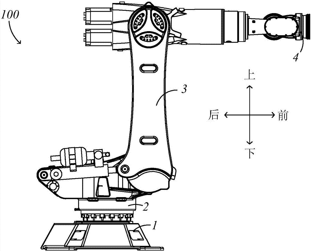
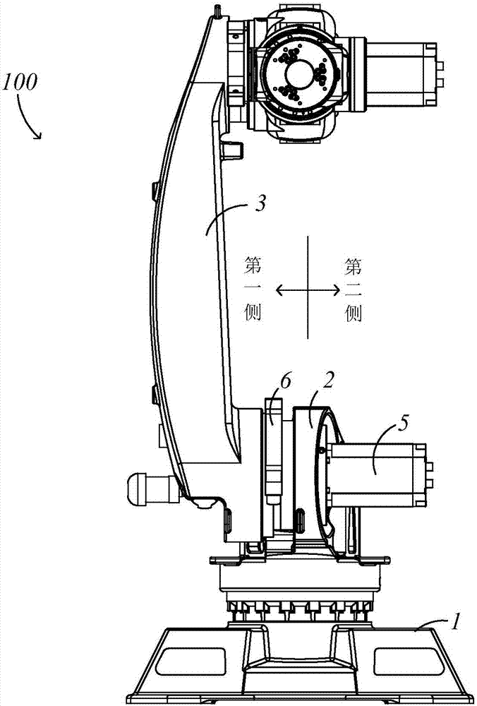
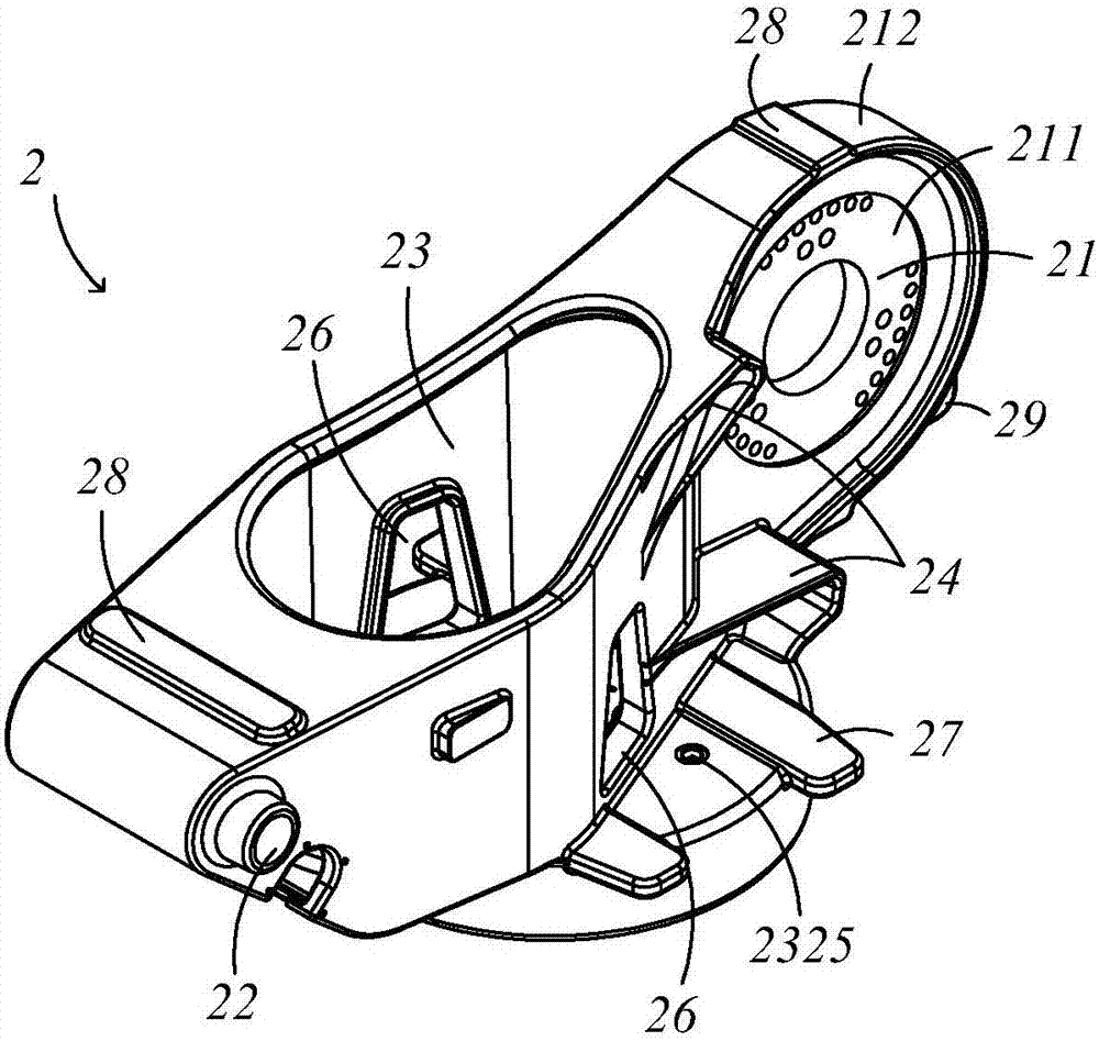
[0031] Such as Figure 1~Figure 2 As shown, the articulated industrial robot 100 includes a base 1, a rocker 2 (or waist part) connecting the first joint and the second joint of the articulated industrial robot 100, a connecting rod 3 (or a big arm), and a Structures such as the operating hand 4 on the connecting rod 3. In order to clearly express the position and direction described in this application, taking the articulated industrial robot 100 as a reference, one end of the upper arm with the operating hand 4 is the front, and the opposite end is the rear end; and the upper arm is located on the upper part of the base 1 .

[0032] One side of the rocker 2 of the body structure of the articulated industrial robot 100 needs to be connected to t...


PUM


Abstract

The invention provides a rocker for a joint type industrial robot. The rocker is provided with a first side, a second side, a front horizontal column, a rear horizontal column, a middle vertical column and a rib plate reinforcement type fixed limiting part, wherein the first side is connected to an RV speed reducer, the second side is opposite to the first side and is connected to a servo motor in a matched mode, the front horizontal column is located in the front and is used for being fixedly connected to the servo motor and the RV speed reducer, the rear horizontal column is opposite to the front horizontal column and is located in the back, the middle vertical column is located between the front horizontal column and the rear horizontal column, and the rib plate reinforcement type fixed limiting part is arranged on the first side of the rocker; the rib plate reinforcement type fixed limiting part protrudes and extends outwards from the first side of the rocker to the direction deviated from the second side. According to the rocker, the rib plate reinforcement type fixed limiting part protrudes and extends outwards from the first side of the rocker to the direction deviated from the second side, the rib plate reinforcement type structure is adopted on the basis of meeting the requirement of function design, and therefore the strength and the rigidity of the rocker are improved and the casting and machining technology performance of the rocker is improved.

Description

technical field [0001] The invention relates to the field of articulated industrial robot manufacturing, in particular to a rocker (or waist part) for articulated industrial robots with excellent mechanical properties such as stiffness and strength and simple processing technology, and a joint with the rocker type industrial robots. Background technique [0002] Nowadays, global cooperation and exchanges in the information age are getting closer, productivity levels and science and technology are constantly improving, and new intelligent manufacturing production methods are about to emerge; industrial robots rely on their flexible, efficient, and high-precision intelligent operation methods. attention. In the current industrial links such as metallurgy, automobiles, and logistics, heavy-duty industrial robots (or articulated industrial robots) are more and more widely used. However, heavy-duty industrial robots must have better load capacity and motion stability, that is, ...

Claims


Application Information

Patent Timeline
Patent Type & Authority Patents(China)
IPC IPC(8): B25J19/00B25J9/12
CPCB25J9/12B25J19/00
Inventor 陆炳融
Owner 昆山华恒机器人有限公司
Learn More