
Ring used for wirelessly remotely controlling smartphone

A smart phone and wireless remote control technology, applied in the field of wireless remote control, can solve problems such as inconvenient operation and use, achieve convenient start and stop, eliminate palm numbness, and facilitate practical promotion and application

Pending Publication Date: 2018-03-06
赵长虹
View PDF7 Cites 6 Cited by
  • Summary
  • Abstract
  • Description
  • Claims
  • Application Information

AI Technical Summary

Problems solved by technology

[0003] Aiming at the inconveniences of the aforementioned existing large-screen smart phones in operation, the present invention provides a new type of ring for wireless remote control of smart phones

Method used


Image

  • Ring used for wirelessly remotely controlling smartphone
  • Ring used for wirelessly remotely controlling smartphone
  • Ring used for wirelessly remotely controlling smartphone

Examples


Embodiment 1

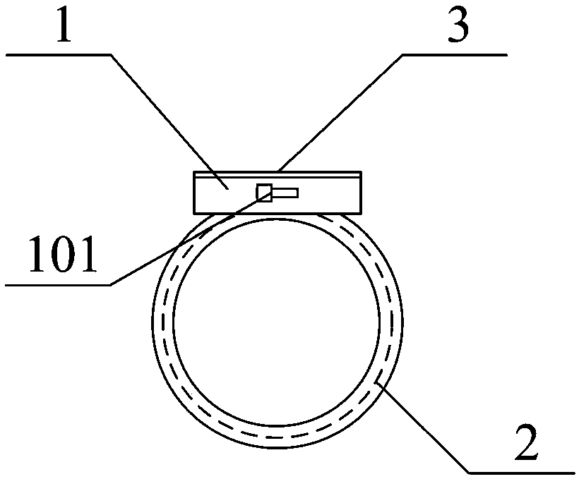
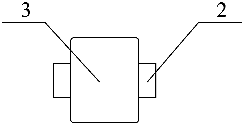
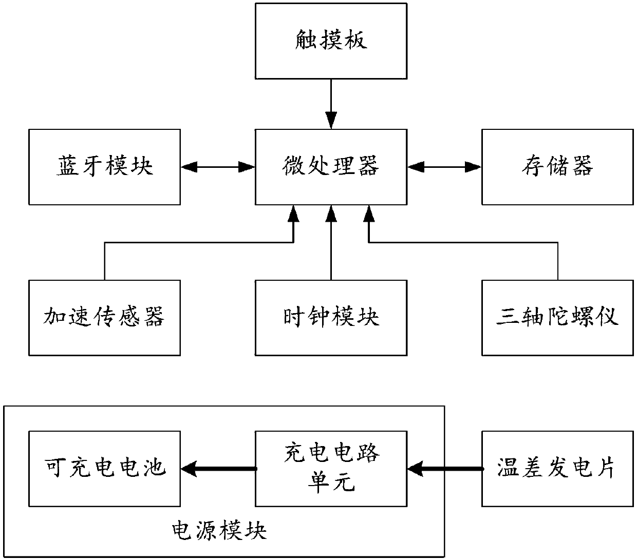
[0020] figure 1 It shows a side-view structure schematic diagram of the first ring for wireless remote control smart phone provided by the present invention, figure 2 It shows the top structural schematic diagram of the first ring for wireless remote control smart phone provided by the present invention, image 3 It shows a schematic circuit structure diagram of the first ring for wireless remote control smart phone provided by the present invention.

[0021] The first kind of ring for wireless remote control smartphone provided in this embodiment includes a ring seat 1 and a ring 2 arranged on the ring seat 1, the ring seat 1 is a hollow box structure, and The inner cavity of the ring seat 1 is provided with a power supply module, a microprocessor, a memory, a three-axis gyroscope, an acceleration sensor, a clock module and a Bluetooth module, and a touch panel 3 is provided on the top of the ring seat 1; The microprocessor communicates with the memory, the three-axis gyro...

Embodiment 2

[0030] Figure 4 It shows a side view structural schematic diagram of the second ring for wireless remote control smart phone provided by the present invention, Figure 5 It shows the top structural schematic diagram of the second ring for wireless remote control smart phone provided by the present invention, Image 6 A schematic diagram of the circuit structure of the second ring for wireless remote control smartphone provided by the present invention is shown.

[0031] This embodiment is another wireless remote control scheme of the first embodiment. The difference between the second ring for wireless remote control of smart phones provided by it and the first embodiment is that: a An operation keyboard 4 is connected to the operation keyboard 4 by the microprocessor.

[0032] Such as Figure 4~6 As shown, in the structure of the second ring for wireless remote control smartphone, the function of the control keyboard 4 is consistent with that of the touchpad 3, and is use...


PUM


Abstract

The invention relates to the technical field of wireless remote control, and discloses a ring used for wirelessly remotely controlling a smartphone. After an operation hand (left hand or right hand) wears the novel ring provided by the invention and wireless Bluetooth connection between the ring and the smartphone is established, the operation hand can carry out single-hand remote control operations including clicking or sliding and the like on the smartphone at any gesture, so that the operation gesture of the operation hand is not constrained, i.e., the user does not need to lift the operation hand to frequently click or slide the screen of the smartphone, a purpose that the user can carry out a remote control operation on the smartphone which is held in the hand or put on a bracket canbe realized in a way that the user is in a quilt and the smartphone is in a trousers pocket or in a naturally drooping palm, so that operation convenience for the smartphone can be greatly improved, and the operation hand can be protected from healthy problems including hand numbness, finger aching pain, deformation and the like. In addition, the ring also has the advantages of convenience in starting and stopping, body temperature power supply, simple structure and the like, and is convenient in practical popularization and application.

Description

technical field [0001] The invention relates to the technical field of wireless remote control, in particular to a ring used for wireless remote control of smart phones. Background technique [0002] With the rapid development of smart phone technology, the size of the display screen of the mobile phone is also getting larger and larger, so as to improve people's viewing experience when viewing videos, pictures or documents. However, with the increase of screen size, the models of smartphones will inevitably increase. For example, there have been 6-inch or even 7-inch large-screen smartphones, which makes one-handed operation more and more unrealistic: When using a large-screen smart phone, you must hold the phone in one hand, and use the fingertips of the other hand (hereinafter referred to as the operator) to perform click or slide operations, in order to realize browsing news, QQ chat content, WeChat content and e-books, etc. operational behavior. However, since the ope...

Claims


Application Information

Patent Timeline
Patent Type & Authority Applications(China)
IPC IPC(8): G06F3/033G06F3/0346G06F3/038G08C17/02A44C9/00
CPCA44C9/00G06F3/033G06F3/0346G06F3/0383G08C17/02
Inventor 赵长虹
Owner 赵长虹
Learn More