
Method for removing white light interferometer interference signal second-order pseudo-coupling point

A white light interferometer and interference signal technology, applied in the field of optical measurement and optical fiber sensing, can solve the problems of reducing measurement accuracy, measurement influence, interference, etc., and achieve remarkable results

Active Publication Date: 2018-03-06
TIANJIN UNIV
View PDF5 Cites 4 Cited by
  • Summary
  • Abstract
  • Description
  • Claims
  • Application Information

AI Technical Summary

Problems solved by technology

Pseudo-coupling points will interfere with the identification of intrinsic coupling points, and will also affect the measurement of polarization-maintaining fiber-related parameters such as extinction ratio, reducing the measurement accuracy

Method used


Image

  • Method for removing white light interferometer interference signal second-order pseudo-coupling point
  • Method for removing white light interferometer interference signal second-order pseudo-coupling point
  • Method for removing white light interferometer interference signal second-order pseudo-coupling point

Examples


Embodiment Construction

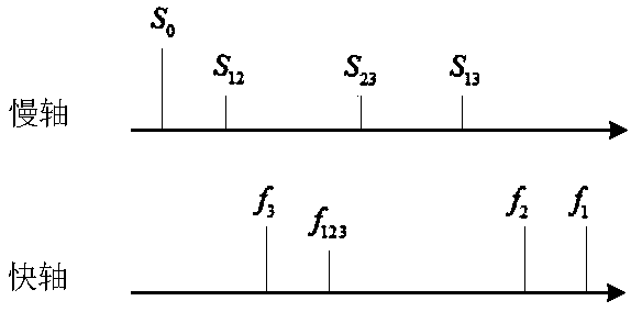
[0026] The experimental device adopted in the present invention is as figure 1 shown. The device consists of eight parts: light source module, polarization-maintaining fiber to be tested, delay module, polarizer, Michelson interferometer, photodetector, data acquisition card, and computer.

[0027] The first part is the light source module, which is composed of a light source and a polarizer. The light emitted by the light source becomes linearly polarized light after passing through the polarizer.

[0028] The second part is the polarization maintaining fiber to be tested. Linearly polarized light is aligned with one of the main axes of the polarization-maintaining fiber and propagates along it, and polarization coupling occurs during the propagation process. Due to the existence of mode birefringence, the light propagating on the two axes produces a certain optical path difference at the exit end of the polarization-maintaining fiber. Under certain conditions, the mode dis...


PUM


Abstract

The invention relates to a method for removing a white light interferometer interference signal second-order pseudo-coupling point. The method is proposed for an experiment device for measuring polarization coupling effect of a polarization preserving fiber through a white light interferometry method. The experiment device comprises a light source module, a polarization analyzer and a Michelson interferometer. A time delay module is added before the polarization analyzer; the time delay module comprises a polarization beam splitter prism, an adjustable light delay line and a polarization beamcombination prism; and the incident end of the polarization beam splitter prism and the polarization preserving fiber are fused together, a fast axis being aligned with a fast axis, and a slow axis being aligned with a slow axis. The polarization beam splitter prism enables the light in two polarization direction in the polarization preserving fiber to be split into two beams of linearly-polarizedlight in space, so that the light transmitted on the slow axis passes through the adjustable light delay line; and through setting of delay amount of the adjustable light delay line, adjustment of optical path difference of the fast axis propagation mode and slow axis propagation mode is realized, and the two modes can be separated in the time domain, thereby preventing generation of the second-order pseudo-coupling point.

Description

technical field [0001] The invention relates to a method for eliminating false coupling points of white light interference signals, and belongs to the technical fields of optical measurement and optical fiber sensing. Background technique [0002] Polarization-maintaining fiber is a special type of single-mode fiber that ensures that the polarization state of linearly polarized light incident along its main axis does not change. Widely used in fiber optic gyroscopes, fiber optic hydrophones, stress temperature sensing, structural health monitoring and other fields. Due to the incomplete symmetry of the internal geometry of the polarization-maintaining fiber, or external disturbances, the originally isotropic material will show anisotropy. This will make part of the energy of the linearly polarized light propagating along one axis of the polarization-maintaining fiber be coupled to the other axis orthogonal to it. This effect is called polarization coupling effect. The pola...

Claims


Application Information

Patent Timeline
Patent Type & Authority Applications(China)
IPC IPC(8): G01M11/02
Inventor 张红霞温国强王宇瑶贾大功刘铁根张以谟
Owner TIANJIN UNIV
Learn More