Polarization fading restraining device and method for white light interferometry sensor array
A polarization fading, sensing array technology, applied in the direction of mitigating undesired effects, can solve the problems of large light energy loss, low light source power utilization, increased cost investment, etc., to improve utilization, simplify evaluation and judgment process, the effect of increasing complexity
- Summary
- Abstract
- Description
- Claims
- Application Information
AI Technical Summary
Problems solved by technology
Method used
Image
Examples
Embodiment 1
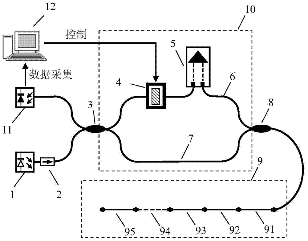
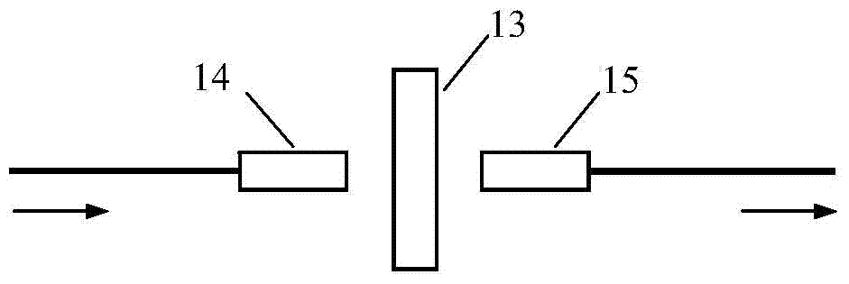
[0034] Such as figure 1 As shown, the anti-polarization fading device of white light interference sensor array consists of broadband light source 1, optical isolator 2, 3dB fiber coupler 3, 8, polarization state adjustment device 4, fiber delay line 5, fiber sensor array 9, photoelectric conversion Device 11 is composed. The wide-spectrum light emitted by the wide-spectrum light source 1 passes through the optical isolator 2 and then is split by the 3dB fiber coupler 3. One of them first passes through the polarization state adjustment device 4 and then passes through the delay line 5 to combine light with the other one using the 3dB fiber coupler 8. After that, it enters the optical fiber sensing array 9 composed of optical fiber sensors 91-95, then returns through the end faces of each sensor and passes through the 3dB fiber coupler 8 to split the light, and after combining the light through the 3dB fiber coupler 3, it is received by the photodetector 11 without polarization...
Embodiment 2
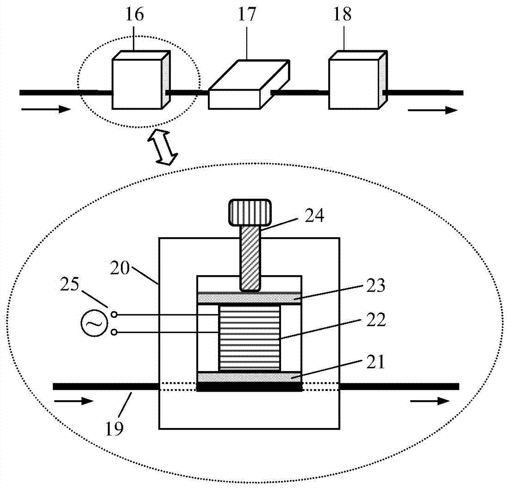
[0039] Such as figure 1 As shown, the anti-polarization fading device of white light interference sensor array consists of broadband light source 1, optical isolator 2, 3dB fiber coupler 3, 8, polarization state adjustment device 4, fiber delay line 5, fiber sensor array 9, photoelectric conversion Device 11 is composed. Wherein the polarization state adjusting device 4 such as image 3 As shown, it is composed of extruded optical fibers to realize the rotation of the polarization state of incident light from 0 to 360°; through the optical fiber extruding devices 16, 17, and 18, they are respectively extruded at 0°, 45° and 0° to the axial direction of the optical fiber Rotate the polarization state from 0 to 360° at three points in the radial distribution of the optical fiber, place the optical fiber 19 at the bottom of the bracket 20, stack the optical fiber pressing plate 21, PZT22, and PZT pressing plate 23 on the optical fiber 19 in sequence, and use the locking screw 24...
PUM
 Abstract
Description
Claims
Application Information
 - R&D
- Intellectual Property
- Life Sciences
- Materials
- Tech Scout
- Unparalleled Data Quality
- Higher Quality Content
- 60% Fewer Hallucinations
Browse by: Latest US Patents, China's latest patents, Technical Efficacy Thesaurus, Application Domain, Technology Topic, Popular Technical Reports.
© 2025 PatSnap. All rights reserved.Legal|Privacy policy|Modern Slavery Act Transparency Statement|Sitemap|About US| Contact US: help@patsnap.com


