


Quick Research
Generate reliable direction feasibility study reports for your R&D in just a few steps.

Technical Q&A
Discover and master advanced knowledge NOW. Basics, ideas, possibilities, all at once.

Find Solutions
As an expert in R&D theories, this can generate solutions to your technical problems instantly.

Evaluate Feasibility
Analyze your overall solution with one click, know your potential R&D risks in advance.

Monitor Landscape
Get weekly tech updates, stay abreast of the latest tech innovations and key insights.
High-accuracy seawater acoustic velocity measurement method based on acousto-optic effect
A measurement method and technology of acousto-optic effect, which are used in measurement devices, measurement of propagation speed, measurement of ultrasonic/sonic/infrasonic waves, etc., can solve the difficulties of ensuring that the ultrasonic travel distance is strictly consistent with the calibration distance, and ensure the accuracy and error. The effect of fast sound velocity profiling
- Summary
- Abstract
- Description
- Claims
- Application Information
AI Technical Summary
Problems solved by technology
Method used
Image

Examples
Embodiment 1
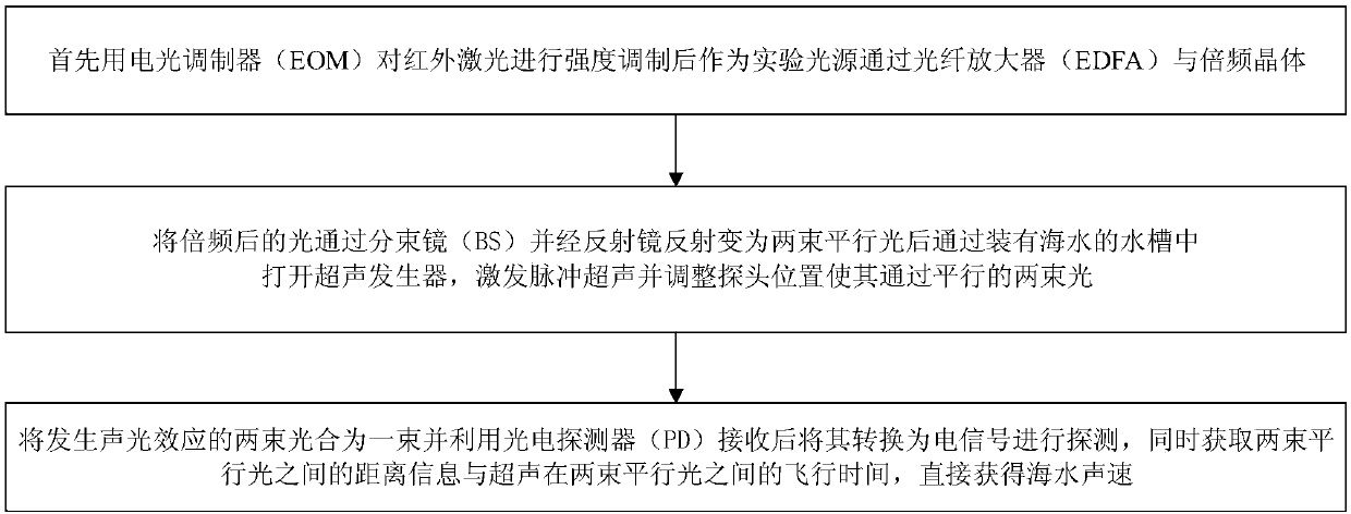
[0049] The embodiment of the present invention introduces a new method for detecting the sound velocity profile of seawater based on the acousto-optic effect, which utilizes the fast and high-resolution properties of the acousto-optic effect. The purpose is to achieve high precision, high stability, fast Seawater sound velocity profile measurement for , see figure 1 , figure 2 , the method includes the following steps:
[0050] 101: Use the electro-optic modulator (EOM) 2 to perform intensity modulation on the infrared light source 1, and the light emitted by the infrared light source 1 is directly connected to the electro-optic modulator (EOM) 2;
[0051]Among them, the main purpose of modulating the infrared light source 1 is to avoid the distance ambiguity problem in the process of measuring the distance using the phase method, that is, when measuring the phase, if the modulation signal has only a fixed frequency, no matter which phase difference measurement method is use...
Embodiment 2
[0063] Combine below figure 1 , figure 2 The specific implementation method of seawater sound velocity profile measurement provided by the embodiment of the present invention will be described in detail.
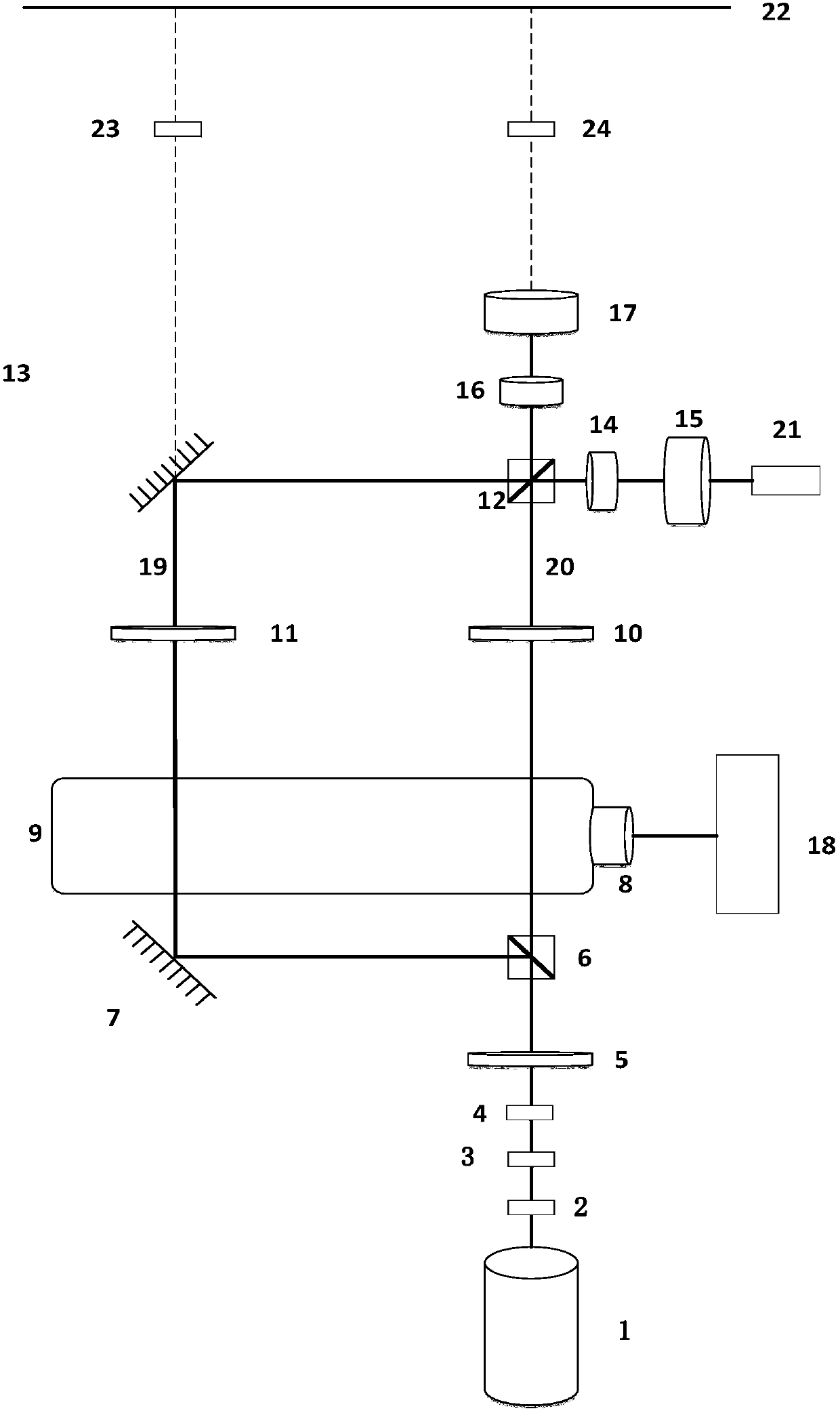
[0064] The embodiment of the present invention is based on the acousto-optic effect, and the optical path is designed as figure 2 shown. The measurement steps are as follows:
[0065] Step 201: if figure 2 As shown, the light emitted by the infrared light source 1 is directly connected to the electro-optic modulator 2 to obtain a modulated light source;
[0066] Step 202: if figure 2 As shown, the optical path is adjusted so that the modulated light source sequentially passes through the erbium-doped fiber amplifier (EDFA) 3, the frequency doubling crystal 4, the first 1 / 2 wave plate 5, the first polarization beam splitter cube 6, and passes through the first reflector After 7 reflections, it can become two parallel light paths and shoot into the water tank 9;
[...
PUM
 Abstract
Description
Claims
Application Information
 - R&D Engineer
- R&D Manager
- IP Professional
- Industry Leading Data Capabilities
- Powerful AI technology
- Patent DNA Extraction
Browse by: Latest US Patents, China's latest patents, Technical Efficacy Thesaurus, Application Domain, Technology Topic, Popular Technical Reports.
© 2024 PatSnap. All rights reserved.Legal|Privacy policy|Modern Slavery Act Transparency Statement|Sitemap|About US| Contact US: help@patsnap.com